Search This Blog

Monday 18 November 2013

Raspberry Pi and Arduino: Running both 5v and 3.3v devices on I2C

Problem Statement:

  1. Arduino UNO is the most prolific version of Arduino board, and runs at 5v DC.  It's I2C interface (Analog pins A4 and A5)  will drive to 5v.
  2. Raspberry Pi runs at 3.3v.  Both of it's I2C interfaces run at 3.3v.
  3. I2C devices purchased through Sparkfun, Adafruit, SeeedStudio, Parallax,  Pololu, can be any combination of 3.3v or 5v

Running a 3.3v I2C device on a 5v I2C bus 
will either destroy the device immediately... 
or more likely... 
significantly reduce it's lifespan. 


So, how do we safely run 3.3v devices alongside 5v devices on the same bus?  
With a Bi-directional Logic Level Converter


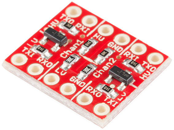
Logic Level Converter:  https://www.sparkfun.com/products/11978


From Sparkfun's Tutorial:

LLC input and output arrowsLLC divided into thirds
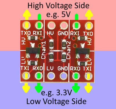
The LLC is designed to be very easy to use. Silkscreen indicators help identify which pins do what. There are twelve pins total – six on each side. We can divide them into groups of three to more clearly define how they relate:
The middle section of the board is where the reference supply for your high and low voltages should go. Supplying voltage to all four of these pins is required. If you’re converting 3.3V to 5V (and vice-versa), for example, you’d run 5V into the “HV” side, and 3.3V into the “LV” input. Make sure each is grounded too!
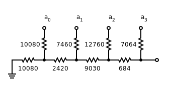
The outer pins correspond to inputs and outputs for channels 1 and 2. Each channel has one voltage divider and one MOSFET shifter.
The labels on these pins – “RXI”, “RXO”, “TXI”, and “TXO” – help describe what each pins does:

  • RXI – High voltage input to voltage divider from high-voltage device. Signal will be shifted down and sent to low-voltage device on “RXO” pin.
  • RXO – Low voltage output from voltage divider to low-voltage device. Signal is shifted down from “RXI” input.
  • TXI – Low voltage input/output of MOSFET circuit. This pin interacts with “TXO” on the high side. Bi-directional, but this is the only shifter that will shift from low to high.
  • TXO – High voltage input/output of MOSFET circuit. This pin interacts with “TXI” on the low side. Bi-directional, but this is the only shifter that will shift from low to high.
To send a signal from the low-voltage side to the high-voltage side (e.g. from 3.3V to 5V), the signal must be input at “TXI”. It’ll pass through the converter and come out as a higher voltage on the “TXO” (transmit output) pin.
On the other hand, a signal that strictly travels from high to low-voltage should pass from “RXI” to “RXO”.
Sending a signal from the high side to the low side is less restricted. We can use either the bi-directional channel or the voltage divider, but we may need to leave the bi-directional channel for converting from low-to-high.


Example Wiring of 3.3v and 5v I2C devices together.

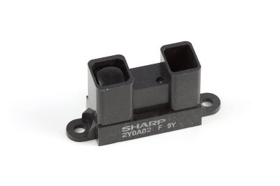
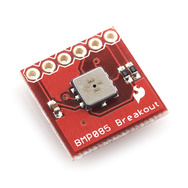
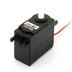
Here, we have an Arduino UNO, an Accellerometer, a Compass, a Barometric Pressure Sensor, and a Raspberry PI all on the same I2C channel.  The neat thing is that with the UNO, as it has a 3.3v regulator on board, you can power  both 3.3v and 5v devices.

Raspberry Pi and Arduino over I2C


References:
Arduino Forum : I2C Bus with 3.3v and 5.0v Device
Raspberry Pi and Arduino linked via I2C
Sparkfun: Using the Logic Level Converter
https://www.sparkfun.com/products/11978

UM10204: I2C-bus specification and user manual Rev5

Sparkfun,
Adafruit,
SeeedStudio,
Parallax,
Pololu,

Thursday 14 November 2013

Out with the Serial, In with I2C - Multimaster - that is...

So I've whined a bit here about some of my hurdles communicating between the Raspberry Pi and the Arduino's, as well as managing critical timing issues on the Arduino.


I spent roughly $30 CDN on the Arduino branded Motor Shield V3 which uses the L293D darlington H bridge driver to provide control over 2 DC motors.

To provide this control, it consumes 8 pins of the Arduino.  6 Digital, and two Analog.

From http://www.instructables.com/id/Arduino-Motor-Shield-Tutorial/ :
There are pins on the Arduino that are always in use by the shield. By addressing these pins you can select a motor channel to initiate, specify the motor direction (polarity), set motor speed (PWM), stop and start the motor, and monitor the current absorption of each channel .
The pin breakdown is as follows:
FunctionChannel AChannel B
DirectionDigital 12Digital 13
Speed (PWM)Digital 3Digital 11
BrakeDigital 9Digital 8
Current SensingAnalog 0Analog 1


It also provides a few handy headers for sensors....  but..... it is not an intelligent device, rather requiring all control code to be written in the Arduino Sketch.


For the same $30 CDN, I just purchased AdaFruit's Motor Shield V2 which uses a pair of Mosfet TB6612 H-Bridges for higher current capabilities to drive four DC motors, or two Stepper motors, or one Stepper and two DC motors...  

These are controlled through the I2C interface.... so not taking up any other Arduino resources.
There are also pin headers that bring Arduino Pins 9 and 10 up for two 5v servos, but these are not I2C controlled...  Maybe on the next revision???  Please Adafruit?

I know, I know, I can add a Adafruit 16-Channel 12-bit PWM/Servo Driver - I2C interface  or stack a Adafruit 16-Channel 12-bit PWM/Servo Shield - I2C interface on top of this one....


Anyway, I expect to have good results out of this controller by the weekend, and fully expect that by using the Servo Timer1 library, I will  remove my timer0 issues regarding  delay() and millis().


References:


Tuesday 12 November 2013

The 3 'R's' - Rethinking my Requirements for a Rover....


This blog entry is just me thinking out loud.. sort of... 

I've got a fair amount of sensory data coming into the rover.  It has three onboard processors, as well as the ability to communicate via wifi to a remote computer if more power is required...

I do not think that I have allocated the correct functions to each processor at the moment....


  • The Rover must be capable of autonomous travel within it's physical capabilities.
  • The Rover must be able to map it's surroundings, and attempt to localize against known landmarks
  • Failing Localization, the rover must create a detailed map of it's surrounding while wandering


This is all pretty much  SLAM mantra... not going to go more into this, at this time, but THIS functionality definitely belongs either on the Raspberry PI, or potentially on the remote CPU.


What makes THIS Rover special....


Sensory Inputs:

Proximity Sensors

  • Four Sharp IR 2Y infrared Distance sensors (20-150cm)  Front/Rear/Left/Right provide near-instantaneous information as to proximity of nearby objects.   Used to avoid collisions, as well as to avoid objects that are moving toward the Rover. (I'll discuss more about my desire to have fight-or-flight characteristics in a later blog.)   These are Analog output sensors, and require code to translate the logarithmic output to distance values.
  • Two MAXBOTIX  MaxSonar EZ1 Sonar Distance sensors (0-6.4m)  pan/tilt pod mounted are used for scanning the surrounds at intervals to create a proximity map of objects within range, and to feed this data to the SLAM algorithms.  These are digital PWM outputs and require simple code to convert pulse width directly to distance. 


Location and Motion Sensors

  • One ADAFruit Ultimate GPS sends serial strings to provide GPS positioning data.  This will become more valuable as the rover size and scope of travel increases... Currently - with a 5meter accuracy -- simply helps localize to a region of a map...

  • Two QRD1114 IR sensors are utilized as wheel encoders (one on each side) currently running in analog comparator mode... My though on single encoders per wheel instead of dual, is that I am using them on the drive wheels, and therefore control the direction of the wheel. I do not need to ascertain it.


  • One Sparkfun ADXL345 triple axis accelerometer. Motion data will be used to compare and validate Wheel Encoder data for positional accuracy.  This is an I2C device. 

  • One Sparkfun HMC6352 compass module. Used to correct "pose" information in the mapping and location functions, also used for trajectory functions.  This is an I2C device. 


Other Environmental Sensors

  • One RHT-03 relative humidity and temperature sensor.  This is a one wire device.

  • One photoresistor  to determine ambient light. Used for adjusting sensitivity on webcam etc... yes..  I know there are algorithms to do this from the camera stream itself, but none of them can be done in a few lines of code and for ten cents...

  • Two condensor microphones, one each side of the rover to determine direction of incoming sounds, as well as simply recording ambient sound or ultimately taking verbal commands.


  • One resistor ladder to provide Battery Voltage information.  This is an analog input that needs to be evaluated against a voltage standard for calibration. 


  • One Standard USB Webcam.  This is used to record images during a "Look" command (look left, look right, look ahead), to record motion when required, or to take scheduled snapshots.


Controlled Outputs:


Motion:


  • Two 6volt DC gear motors.   The Rover uses differential drive.  Wheel encoders assist in maintaining speed and course correction. 

  • Two servo motors for pan and tilt function of Sonar/Webcam pod.

Signalling and Communication:


  • One bank of 9 Bright White LEDs  located on pod for illumination.


  • One bank of  6 High Intensity Infrared LEDs located on pod for dark illumination. (can also be modulated and used to control external IR devices)
  • Four Bright RED LEDs, situated on each corner as "turn signal" indicators. 
  • One Laser Diode located on pod for identifying remote objects. (ok... it's a simple laser pointer...)  This may potentially be used for parallax range finding.
  • One  one inch audio transducer for use as audio out to communicate, or as a "in motion"  beeper when required. 


Distributing the workload appropriately:

Over the course of the next week, I will be re-working the who-does-what for each processor as follows:

Raspberry Pi  
  • will provide central control and communications with Web Console and Database.
  • will provide for mapping and localization
  • will manage both audio input and output.
  • will become I2C master for ALL input and output devices. 
  • will record GPS data to database
  • will record compass data to database, and provide to Arduino UNO for course correction
  • will record accelerometer data to database
  • will record environmental data to database.
  • will manage clean shutdown on low power. 
  • (future state will return to charging dock)
  • will manage USB webcam 

Arduino UNO 
  • will be set up as an I2C slave.
  • will control the two DC motors via the MotorShield, and read the two QRD1114 encoders to keep the motor speeds / distance travelled accurate.  
  • will monitor and manage the four Sharp IR proximity sensors for localized range sensing.
  • will manage "fight-or-flight" reaction for obstacle avoidance even while at rest.
  • will monitor battery condition.

Arduino FIO
  • will manage pan and tilt servos for pod.
  • will manage MAXSonar EZ1 front and rear pod mounted range finders. 
  • will manage Bright White illumination 
  • will manage High Intensity IR illumination
  • will manage Laser pointer
  • will manage signaling LEDs


wish me luck....  


Sunday 10 November 2013

The case for lurking on LMR before starting on a large (ish?) robotics venture...

Ok... so let me start with...

 I've been humbled by the sheer simplicity with which some of these bots on LMR (Lets Make Robots) are made.  Functional and clean.


The one article that has made me rethink my strategy the most is  Oddbot's article Pushing the limits with encoders

In my Robot here, I use a RaspBerry Pi to talk to two Arduino's via Serial over USB.  The premise being that the USB was already there for programming... might as well use it for communications. Then one of the Arduino's is also an I2C master to various sensors, that it then translates into serial feeds for the RPI.... hmmmmm....  can anyone say "inefficient"? 

I *had* investigated the option of using the RPI as a I2C master, and the two Arduino's, along with all of the I2C sensors would become slaves... looking back, I passed up on this quickly because I would have had to build or buy a level converter.... really?

I've spent probably close to $500-$600 on this thing so far... and yet a few bucks... or more likely an hour at the soldering iron made my decision for me.


I've struggled for WEEKS on timing issues related to getting commands accurately into the Arduino running the motors (using the Motorshield V3) which uses two PWM drivers, as well as the two servos .... The UNO fully consumes Timer 0/1/2 to take care of these, and so all code has to be devoid of "delay()" or "millis()"....  Sending a Serial command formated with specific start character, as well as a command UID to be used to validate completion of the command back to the RPI.

So.....

I'm going to step back for a week... regroup... reassess what functions are best suited to which processor, and clean it up.

Raspberry PI being I2C Master.   Arduino UNO retaining Motor control as well as Wheel encoder and IR proximity, but as an I2C slave as opposed to "Serial - hope-it-gets-interpreted-properly".
As I was simply replaying the I2C sensors via serial for the RPI to interpret, store, react, anyway.... This will be a workload removed from the UNO.
I will still dedicate the Arduino FIO to managing the Sonar POD servos and MAXSonar EZ1s, for now... but will communicate with the RPI as an I2C slave.

I may ultimately be able to eliminate one of the Arduino's .... but we'll save that for the next robot.

Any suggestions, tips, words of kindness... laughter...  bring it on...


References:

http://blog.oscaraConnect Raspberry Pi and Arduino with Serial USB Cable
Raspberry Pi and Arduino Connected Using I2C
Raspberry Pi and Arduino Connected Over Serial GPIO
Step by Step Guide on Making an I2C Slave Device with an Arduino
Arduino.cc: Arduino as I2C Slave ?
Instructables: I2C between Arduino's
http://digitalcave.ca/resources/avr/arduino-i2c.jsp
Raspberry Pi master controls Arduino UNO slaves via I2C
I2C communication between a RPI and a Arduino


Tuesday 5 November 2013