I've had a few informative back and forth emails with Nikki V from Freescale regarding my failure to get connected to Repetier Host from the Marlin Firmware on my Teensy 3.1.
As mentioned in my previous article, I was finally able to compile and install the Marlin Firmware when I used the fork that Paul Stoffregen started, along with Nikki's Configuration.h and pins.h files. However, I could not connect to the firmware with Repetier.
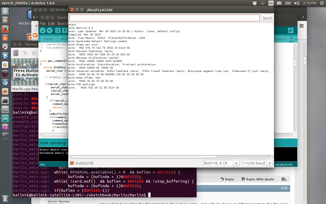
Marlin was sending the appropriate communications out through the USB serial port, as evidenced by this screenshot:
But the Repetier connect request was not initializing Marlin, and returning the printer information.
Nikki pointed me back to the same thread on the Teensy Forum that I've already read 100 times...
Yeah... but I'm apparently blind or ignorant... or both...
She brought my attention to the fact that this issue has already been identified, and could be remediated by clicking a "fake OK" button from within the Manual control page.
I couldn't find the "Fake OK" button, so I read a little deeper.
And then Paul chimed in with a comment about compiling on Linux, and it all came together... Thank you Nikki, Thank you Paul.
Here's what Paul had to say that made all the difference:
I tried the Linux version. It also has only "OK", not "Fake OK", but it seems to work fine.
I had to edit the baud rate to 57600 in Configuration.h. The Linux
driver doesn't seem to like 250000 (even though Teensy 3.1 complete
ignores the baud rate).
Repetier-Host does seem to be getting hung up on something and requires
the "OK" button clicked. I believe it's due to the missing temperature
feature. The blue bar will stay stuck as "1 Command Waiting". Clicking
"OK" gets it unstuck.
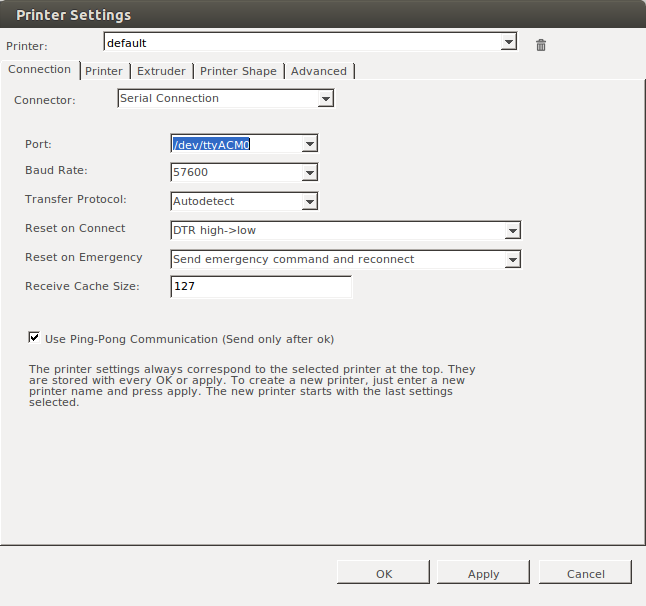 I set the baudrate in configuration.h to 57600, and recompiled and uploaded to the Teensy 3.1. I then launched Repetier, and went into the printer configuration, and selected 57600.
I applied, saved, and hit "Connect" .....
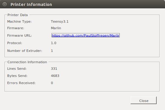
And Voila!
Marlin Firmware now connects, and provides printer information.
As of today, I have hard wired in 100k thermistors for Extruder and Bed heater temperature sensing, and set the pullup resistors for the endstops...
The Quadrature encoders are functioning on X and Y axis via the Flextimer module
QuadDecode library, and
*MY* PID routines (using the Arduino PID library)
are successfully driving both X and Y axis DC motors from the manual controls in Repetier.
The Quadrature encoders are functioning on Z axis with Phase A/B hardware pin interrupts , and
*MY* PID routines
are successfully driving one Z axis DC motors from the manual controls in Repetier.
I have a functional I2C 20x4 LCD display, as well as SDcard reader.
As far as capacity on the Teensy, here is the size of code - all in - so far:
From the Arduino IDE:
Binary sketch size: 108,816 bytes (of a 262,144 byte maximum)
Estimated memory use: 14,080 bytes (of a 65,536 byte maximum)
Is
it running... sure... is it printing... no... my budget hasn't allowed
me the pleasure of a real extruder. I'm simply stepping a NEMA17 I had
kicking around. I keep saying "next paycheck!"
TODO:
- Acquire a real extruder/hotend (today I'm simply driving a NEMA17 that I had kicking around.) (anyone want to help?? LOL)
- Wire up FET transistors to drive extruder and bed heater elements
- Wire up endstops
- Lots and lots and lots of PID tuning. Things have changed since porting/merging my DC motor code into the Marlin Firmware.
- Take video this weekend and upload to Youtube! LOL
- Remove MY PID routines, and create macro/wrapper to use existing Marlin PID routines meant for temperature management.
- Put "conditional" code back in so I can merge this stuff back to github
- Figure out how to merge stuff back to github
- figure out whether 7. or 8. should come first...

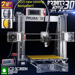 This past weekend, I finally had the time to start building my Reprap Prusa i3 3D Printer, which I ordered a few weeks ago from Shenzhen Sunhokey Electronics Co., Ltd. on
Aliexpress.com
This past weekend, I finally had the time to start building my Reprap Prusa i3 3D Printer, which I ordered a few weeks ago from Shenzhen Sunhokey Electronics Co., Ltd. on
Aliexpress.com


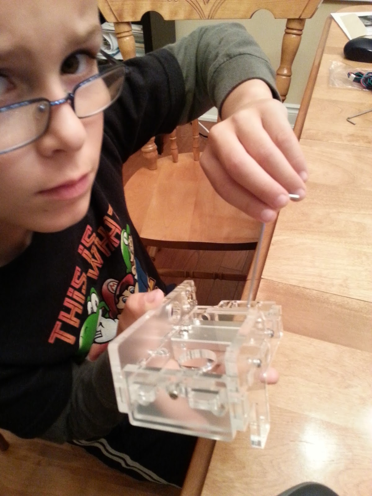


 I wrapped up for the weekend at this point. Two days of "duration", and about 6 hours of "effort".