
This blog entry is just me thinking out loud.. sort of...
I've got a fair amount of sensory data coming into the rover. It has three onboard processors, as well as the ability to communicate via wifi to a remote computer if more power is required...
I do not think that I have allocated the correct functions to each processor at the moment....
- The Rover must be capable of autonomous travel within it's physical capabilities.
- The Rover must be able to map it's surroundings, and attempt to localize against known landmarks
- Failing Localization, the rover must create a detailed map of it's surrounding while wandering
This is all pretty much SLAM mantra... not going to go more into this, at this time, but THIS functionality definitely belongs either on the Raspberry PI, or potentially on the remote CPU.
What makes THIS Rover special....
Sensory Inputs:
Proximity Sensors
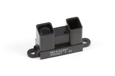
- Four Sharp IR 2Y infrared Distance sensors (20-150cm) Front/Rear/Left/Right provide near-instantaneous information as to proximity of nearby objects. Used to avoid collisions, as well as to avoid objects that are moving toward the Rover. (I'll discuss more about my desire to have fight-or-flight characteristics in a later blog.) These are Analog output sensors, and require code to translate the logarithmic output to distance values.
- Two MAXBOTIX MaxSonar EZ1 Sonar Distance sensors (0-6.4m) pan/tilt pod mounted are used for scanning the surrounds at intervals to create a proximity map of objects within range, and to feed this data to the SLAM algorithms. These are digital PWM outputs and require simple code to convert pulse width directly to distance.

Location and Motion Sensors
- One ADAFruit Ultimate GPS sends serial strings to provide GPS positioning data. This will become more valuable as the rover size and scope of travel increases... Currently - with a 5meter accuracy -- simply helps localize to a region of a map...

- Two QRD1114 IR sensors are utilized as wheel encoders (one on each side) currently running in analog comparator mode... My though on single encoders per wheel instead of dual, is that I am using them on the drive wheels, and therefore control the direction of the wheel. I do not need to ascertain it.

- One Sparkfun ADXL345 triple axis accelerometer. Motion data will be used to compare and validate Wheel Encoder data for positional accuracy. This is an I2C device.

- One Sparkfun HMC6352 compass module. Used to correct "pose" information in the mapping and location functions, also used for trajectory functions. This is an I2C device.

Other Environmental Sensors
- One RHT-03 relative humidity and temperature sensor. This is a one wire device.

- One photoresistor to determine ambient light. Used for adjusting sensitivity on webcam etc... yes.. I know there are algorithms to do this from the camera stream itself, but none of them can be done in a few lines of code and for ten cents...
- Two condensor microphones, one each side of the rover to determine direction of incoming sounds, as well as simply recording ambient sound or ultimately taking verbal commands.

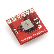
- One BMP085 Barometric pressure sensor. This is an I2C device.

- One resistor ladder to provide Battery Voltage information. This is an analog input that needs to be evaluated against a voltage standard for calibration.

- One Standard USB Webcam. This is used to record images during a "Look" command (look left, look right, look ahead), to record motion when required, or to take scheduled snapshots.
Controlled Outputs:

 Motion:
- One Arduino MotorShield (V3). This shield provides PWM control through an L298 dual H-bridge for two DC motors with current sensing.
- Two 6volt DC gear motors. The Rover uses differential drive. Wheel encoders assist in maintaining speed and course correction.
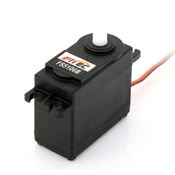
- Two servo motors for pan and tilt function of Sonar/Webcam pod.
Signalling and Communication:
- One bank of 9 Bright White LEDs located on pod for illumination.
- One bank of 6 High Intensity Infrared LEDs located on pod for dark illumination. (can also be modulated and used to control external IR devices)
- Four Bright RED LEDs, situated on each corner as "turn signal" indicators.
- One Laser Diode located on pod for identifying remote objects. (ok... it's a simple laser pointer...) This may potentially be used for parallax range finding.
- One one inch audio transducer for use as audio out to communicate, or as a "in motion" beeper when required.
Distributing the workload appropriately:
Over the course of the next week, I will be re-working the who-does-what for each processor as follows:
Raspberry Pi
- will provide central control and communications with Web Console and Database.
- will provide for mapping and localization
- will manage both audio input and output.
- will become I2C master for ALL input and output devices.
- will record GPS data to database
- will record compass data to database, and provide to Arduino UNO for course correction
- will record accelerometer data to database
- will record environmental data to database.
- will manage clean shutdown on low power.
- (future state will return to charging dock)
- will manage USB webcam
Arduino UNO
- will be set up as an I2C slave.
- will control the two DC motors via the MotorShield, and read the two QRD1114 encoders to keep the motor speeds / distance travelled accurate.
- will monitor and manage the four Sharp IR proximity sensors for localized range sensing.
- will manage "fight-or-flight" reaction for obstacle avoidance even while at rest.
- will monitor battery condition.
Arduino FIO
- will manage pan and tilt servos for pod.
- will manage MAXSonar EZ1 front and rear pod mounted range finders.
- will manage Bright White illumination
- will manage High Intensity IR illumination
- will manage Laser pointer
- will manage signaling LEDs
wish me luck....
No comments:
Post a Comment