

Pictured here, to the right, is the frame I made up to house the Y-Axis table. You can see the carriage assembly, motor and rail running horizontally in this image. There are ball bearing slider rails in the "top" and "bottom" sections of the frame that will be attached to the Y-Axis carriage and table.
The frame itself is made from 3 inch extruded Vinyl exterior railing. It is 28" long to accommodate the travel of the Y-Axis table, and it is 16" wide. I will be putting threaded adjustable feet in each corner for leveling. The ball bearing slider rails fit very snugly inside the extrusion.
I have laid the X-Axis carriage and rail across it, simply to visualize the mounting options and location.
Now: On to the good stuff...

They are driven by brushless 12v DC motors, and have a high resolution rotary optical encoder on the end of the hollow paper feed shafts.
My train of thought is something like this...
If I were to cut the hollow shafts short... say 3 inches in length, then support them with bushings, I could cement a threaded rod inside them, and theoretically create a Z-Axis identical in function to many of the existing Reprap stepper motor Z-Axis implementations. But with 0.08mm resolution....
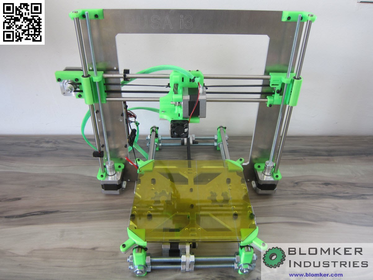

This is RepRrap Prusa implementation using two Z-Axis steppers...
This is just another view of the potential Z-Axis assemblies I have to work with.
I have another couple days until I'm home again to work on them. I would *love* to get some input and ideas as to how I should/could implement this.
Comments please...
No comments:
Post a Comment