Search This Blog

Showing posts with label robotics. Show all posts

Monday, 30 March 2015

Connecting to those underside pins on the Teensy 3.1

This is a VERY short post to describe how "I" connected permanently to the underside pins on my Teensy 3.1's

 
To get access to the extra pins on the bottom of the teensy, I used a dual row header, and bent the inside pins at a 90 degree angle, trimmed, and soldered. That's it.  Easy peasy!


This shot shows the Real Time Clock crystal soldered into place. 

There's some further discussion on the subject here...  

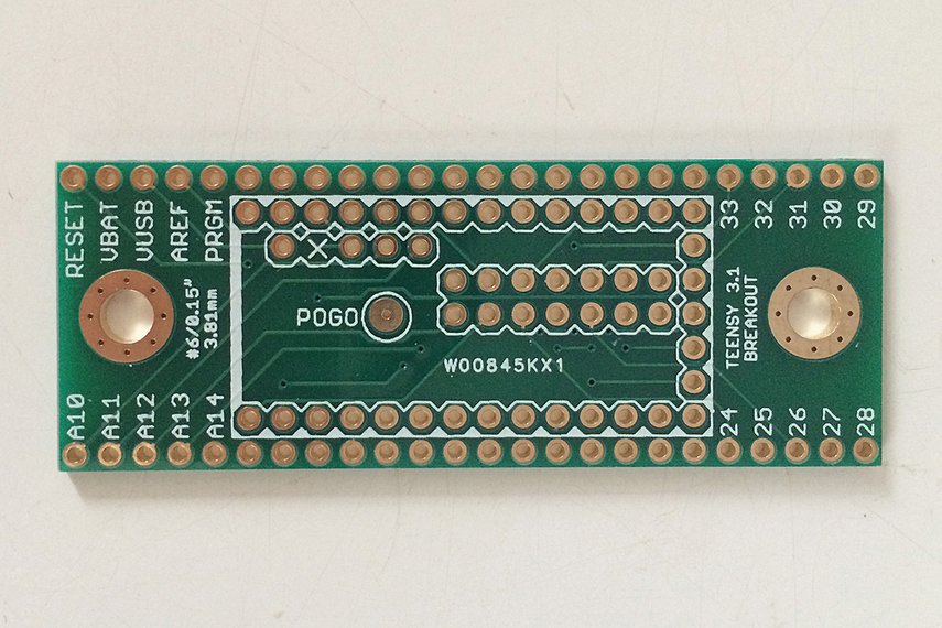
There are also breakout boards designed to give you easy access to these pins...


Thursday, 4 December 2014

Should I port SLAM to the Raspberry Pi's unused GPU on my Autonomous Rover?


Right now, I use Arduinos for motor control (PID control for encoders and dc motor) as well as aggregating sensor data and feeding the Raspberry Pi on my Autonomous Rover.

The Pi runs a live stream webcam for the rover, manages the webpage control console, and maps the environment for dead reckoning navigation.  This is a lot of work for one little CPU.

I've recently seen a few articles on using the dormant GPU on the Pi. and though that Simultaneous Localization and Mapping (SLAM) would be perfectly suited for the GPU's capabilities. Real world mapping and localization should be practically identical to Video Game based algorithms... It's been almost a year since Broadcom opened up the specs for this chip.

I would also use the GPU for calculating shortest path via A* routines. 

So... has anyone looked into this? 
 (And yes... I "Googled" it first...)


References:

Andrew Holme: Accelerating Fourier transforms using the GPU
Pete Warden: How to optimize Raspberry Pi code using its GPU
GPGPU hacking on the Pi
Hacking The GPU For Fun And Profit (Pt. 1) 
Broadcom released the specs for the VideoCore IV GPU
SLAM: Remotely-Processed Visual SLAM Using Open-Source Software 


Tuesday, 15 July 2014

Developing a Robot Shield for Teensy 3.1: Looking for feedback

The many features and beautiful simplicity of the venerable Arduino, have captured the minds and imaginations millions of hobbyists, programmers, and Roboteers.  

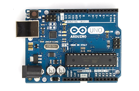
Arduino, as a company, has created a diverse number of boards as Open Source Hardware . This diversity caters to various physical, electrical, and I/O requirements, allowing for a broad spectrum of applications.   That said, an entire industry has sprung up around reproducing variants of the Arduino

All of these boards, however,  have two things in common.  
  1. They use Atmel AVR 8bit microcontrollers (Typically ATmega328 or in the case of the Mega - ATmega1280 or 2560)
  2. They have an Arduino bootloader installed to allow quick and convenient development/upload cycles with the Arduino IDE.


One of the most recent trends, has been to reproduce the Arduino form factor, complete with I/O, A/D and D/A for other microcontrollers, to allow them to utilize the hundreds (thousands?) of "shields" developed to support the Arduino family. 

Many of these alternative boards have also provided plug-ins (cross compilers and compatible libraries) for the Arduino IDE, to allow a smooth transition from the comfort of developing for the Arduino's 8bit AVR chip to a more complex 16 or 32bit microcontroller.


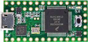
Today, I'm going to discuss the   Teensy 3.1.  

https://www.pjrc.com/teensy/teensy31.html 

Although not pin compatible with the Arduino family, it does leverage the Arduino IDE through Teesyduino for quick application development, while hopefully grooming it's users to step into more robust ARM development tools.  If UNO form factor compatibility is a requirement (for instance to use an existing shield) then the Teensy Development board from PetitStudio will do the trick.


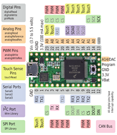
The Teensy 3.1 is based on the   Freescale K20P64M72SF1 ARM Cortex M4 processor. It runs at 96Mhz, has 256K flash, and 64k RAM, 43 digital I/O, 21 Analog inputs, 12 PWM outputs,  12 Timers, 2 I2C ports, and 4 Serial UARTS.  Whew...

In addition to that, there are two TRUE Analog to Digital Converters that can be read simultaneously ie: no multiplexing inputs. Currently, Pedvide's ADC library can be used to access both ADCs. Thanks to Freescale, there is also a CAN Bus
(Controller Area Network - communication channel used in automobiles) Libraries for this will be available shortly.


Comparison Of Arduino UNO R3, Mega2560, and Teensy 3.1 specifications
Technical Specifications
Feature Arduino
Uno R3
Arduino Mega2560 Teensy 3.1 Units
Price 25 54 19.8 US Dollars
Processor Atmega328 ATMega2560 MK20DX256VLH7
Bits 8 8 32
    Core AVR AVR Cortex-M4
    Rated Speed 16 16 72 MHz
    Overclockable 24 24 96 MHz
Flash Memory 32 256 256 kbytes
    Bandwidth 16 16 192 Mbytes/sec
    Cache 0 0 256 Bytes
RAM 2 8 64 kbytes
EEPROM 1 4 2 kbytes
Direct Memory Access N/A N/A 16 Channels
Digital I/O 14 54 34 Pins
    Voltage Output 5 5 3.3V Volts
    Voltage Input 5 5 5V Tolerant Volts
Analog Input 6 16 21 Pins
    Converters 1 1 2
        Resolution 10 10 16 Bits
            Usable 10 10 13 Bits
        Prog Gain Amp 0 0 2
    Touch Sensing N/A 64 12 Pins
    Comparators 1 1 3
Analog Output 0 0 1 Pins
    DAC Resolution - - 12 Bits
Timers 3 6 Total 12 Total Pins
    FTM Type 0 0 3
        PWM Outputs 6 12 12
    PDB Type 0 0 1
    CMT (infrared) Type 0 0 1
    LPTMR Type 0 0 1
    PIT (interval) Type 1x8bit 2x16bit 2x8bit
 4x16bit
4
    Systick 0 0 1
    RTC (date/time) ** 0 1 1
Communication
    USB 1 1 1
    Serial 1 0 3
        With FIFOs 0 0 2
        High Res Baud 0 0 3
        Fast Clock 0 0 2
    SPI 1 1 1
        With FIFOs 0 0 1
    I2C 1 1 2
    CAN Bus 0 0 1
    I2S Audio 0 0 1
        FIFO Size 0 0 8


Now, if you've happened to get this far, here is the meat of this article:
There are few "shields" available for the Teensy as yet. There are a few adapters that provide UNO form factor, there is an audio shield, a TFT display shield, and a Smartmatrix shield, as well as a few other special use shields. 

What I am looking to develop, is a multifunction shield that maintains the small size of the teensy as much as possible, but incorporates a 9dof  like the LSM9DS0 Teensy 3.1 Micro Shield, as well as an l293d to drive two small DC motors. I2C, as well as Remaining I/O will be brought out to right angle headers on the edge of the shield.  

Before I complete the board design, I'm looking for feedback, motivation, and warnings (like "that l293 is going to get too hot!") ... 

 Cheers.


References:

https://www.pjrc.com/teensy/K20P64M72SF1.pdf
http://cache.freescale.com/files/32bit/doc/ref_manual/K20P64M50SF0RM.pdf 
http://cache.freescale.com/files/32bit/doc/quick_ref_guide/KQRUG.pdf


My Teensy Playlist on Youtube  


http://www.freescale.com/webapp/sps/site/prod_summary.jsp?code=K20_72
https://www.pjrc.com/teensy/td_libs_USBHostShield.html
OSH Park: SmartMatrix Shield for Teensy 3.1 
https://community.freescale.com/thread/320695 
http://hackaday.com/2013/12/09/meet-the-teensy-3-1/ 

http://trippylighting.com/category/uncategorized/
SmartMatrix Shield for Teensy 3.1
Adafruit 2.8" TFT Touch Shield for Arduino for Teensy 3.1
https://www.tindie.com/products/loglow/teensy-31-breakout/
http://petitstudio.blogspot.ca/2014/04/teensy-3-development-board-arduino.html
Audio Adapter Board for Teensy 3.0 & 3.1 and OctoWS2811 Adapter for Teensy 3.1 – Control tons of NeoPixels!
http://www.mccauslandcenter.sc.edu/CRNL/tools/oscilloscope
Github: KurtE- Modified version of Trossen Bioloid library to user Serialx objects
https://github.com/KurtE/Teensy3.1-Breakout-Boards
http://zentasrobots.com/
http://www.circuitsathome.com/category/mcu/arduino/usb-shield

http://forum.pjrc.com/threads/26017-Teensy-3-1-and-9DOF-Stick-I2C
https://github.com/ptrbrtz/razor-9dof-ahrs/pull/20
https://www.tindie.com/products/onehorse/lsm9ds0-teensy-31-micro-shield/ 
https://github.com/Poofjunior/RaspPi-Teensy-USB-ServoController 


Development tools:
PCJR.com : Teensyduino IDE extension
http://www.seanet.com/~karllunt/bareteensy31.html 
http://embedxcode.weebly.com/ 
http://www.uTasker.com/freescale/Teensy_Simulator.zip
http://www.mentor.com/embedded-software/sourcery-tools/sourcery-codebench/overview/ 
Teensy 3.0 now supported by the USB Host library
Freescale Hack It Together (H.I.T.) Project Initiative - Get Excited!


Friday, 25 April 2014

PenguinBot Self Defence - or How to Arm a Penguin


Over on Hack-A-day, one of the readers joked that I should have Nerf Launchers on the PenguinBot:


And given that today *IS* World Penguin Day , I thought I would spend some time this weekend to add some more playfulness to PenguinBot.
(Disclaimer: I am not affiliated with World Penguin Day or GreenPeace. I apologise if you find this article is in poor taste.)

In a previous update, I had mentioned that I was working on changing Operating Modes from full manual, to Wandering with Object Avoidance, to Following a light with sound activation or Hand Claps.  

I live in a house with three young children...  There is no such thing as "Ambient Sound" in my house to set a reasonable threshold.  (Seriously!!!) 


Additionally, Penguins were not meant to be tethered!  Not even for programming! 

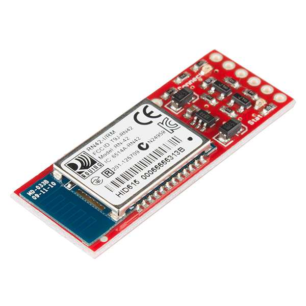
So... I've installed Bluetooth!  

I can now command this Penguin from the comfort of my chair! 


And to appease the readers of Hack A Day ....  
I'm installing a Penguin Self Defence system. 

No more will my PenguinBot be at the mercy of marauding sharks! 

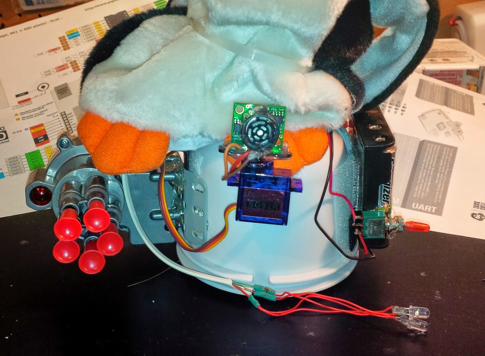
I found this in my junk drawer.  I believe it came off of a kids remote  control car. It has a simple geared DC motor.
As I only need to run it in one direction, I can turn it on and off with a transistor.  


As you can see here, the Nerf Launcher fits nicely on the opposite side as the battery pack.  AND as an added bonus, it offsets the weight of the batteries which had the annoying effect of causing the forward motion to pull to the left. 

Below find the new and improved schematic diagram of PenguinBot V2.0.


I will be wiring this up over the weekend, adding some sequencing to randomly shoot in the direction of bright lights, and uploading the videos.

Cheers, and have a great weekend.  You bet I will...


References:
http://worldpenguinday.com/
http://playground.arduino.cc/Learning/Tutorial01
http://www.instructables.com/id/Android-talks-to-Arduino/
http://learn.adafruit.com/downloads/pdf/adafruit-arduino-lesson-13-dc-motors.pdf
https://sites.google.com/site/stembotics/projects/bluetooth
http://en.wikipedia.org/wiki/Obstacle_avoidance
http://www.instructables.com/id/Arduino-Object-Avoidance-Robot/

Wednesday, 23 April 2014

Followup on 3D printer from Scavenged DC Motor / Encoders Blog

One word...  Wow!

You guys are both supportive and educational at the same time.  

Yes... many of you either told me not to bother because I was simply reinventing the wheel (I actually appreciate that the most because many of you provided links to prior art!), or that I was just plain foolish to attempt this... (but if you are going to criticize, back it with facts/links)...

But MANY of you (over 100 as of this writing) have provided me with positive reinforcement, and sent me links and articles showing others who have succeeded on this journey in one way or another.

I just want to talk a minute about the differences between a "Stepper Motor"  a "DC Motor" and a "Servo Motor".  

I've linked each of the above to Wikipedia so that I don't have to go into great detail of how each actually works.  I'm more interested in the differences each presents in the context of fine grain positioning control.


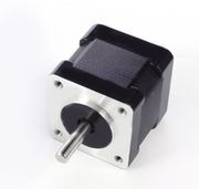
A Stepper motor has multiple coils that when energised in a certain sequence, produces defined accurate "steps" of the shaft. The NEMA 17 Stepper Motor shown here, seems to be the DIY 3D printer industry's  favorite. It provides 1.8° per step accuracy. As long as your software can initialize the linear travel with endstop switches, mechanical or optical, then it will know at all times where along the axis it was left. There is little issue with "drift".  When you cut the power to a stepper motor, it stays exactly where you placed it. Yes, of course you can "push" the carriage without power but for the most part an energized step will place the shaft in a known spot.  Speed is managed by the frequency in which you cycle the steps.


A DC motor, on the other hand is pretty much "free running".  You apply a DC voltage to the winding, and the shaft will spin in one direction.  Reverse the polarity and the shaft will spin in the other direction.  Torque is based on electric current capabilities, and is a factor of the wire gauge and number of windings.  Speed is related to the voltage applied.  Most DC motors in a control context are driven via Pulse Width Modulation or PWM, but still have no feedback as to the position of the shaft, or in my case linear carriage.  When you remove power from a DC motor, it will coast until it stops.  To remedy this, you need to employ Dynamic Braking. Accuracy is non Existent.


A Servo Motor, starts with a DC motor, but provides a feedback mechanism for the angle of rotation.  The hobbyist style servos shown to the right here, rely on a potentiometer, attached to the motor shaft by gears.  The position of the shaft is directly related to the value of the potentiometer. 

Commercial Servo Motors will employ magnetic, electric, or optical Encoders to sense rotational (or linear) movement, and provide this feedback to a servo controller. 

 A Servo Motor is basically a closed loop system that provides direct feedback to the controller upon any movement of the shaft.  Accuracy is a product of the resolution of the encoder in use.


To that end, what I am proposing in my project, is to make a set of Linear Servo Motors.
I will drive them with Pulse Width Modulation as a DC motor.  I will provide feedback, monitoring the encoder position through Interrupts, and thus essentially create a linear servo motor.  In addition, I will apply the appropriate functions to slow the carriage in advance of the destination so as not to overrun the target. Photo interrupters will be used at each end of the carriage for periodic self calibration.


Here are a few of the links shared with me:

Here is an example of a Thing-o-matic makerbot 3d printer with DC motors and linear encoders:


Apparently the GeckoDrive is a popular solution in this space, it takes the outputs meant for a stepper, and manages a DC motor / encoder loop.


Then there's Rapy, a DC motor powered 3D printer made in Korea
It uses two DC Gear motors and one Rotary Optical Encoder per axis.


Somewhat unrelated, but a very interesting belt drive linear motion system using 80/20 extrusion as the linear rail.


More to read:

Converting an Ordinary DC Motor to a Servomotor
http://www.motioncontroltips.com/category/encoders/l-encoders/
https://www.youtube.com/watch?v=wBnbQrs6JsQ
http://blog.machinekit.io/p/machinekit_16.html?m=1
(http://www.geckodrive.com/geckodrive-brush-dc-drives/g320x.html
http://www.geckodrive.com/gecko/images/cms_files/images/G320XStepDirectionCircuit.jpg \
Makeatronics: Building a 3D printer
Makeatronics: 3D Printer Motor Control - Part 1
https://groups.google.com/forum/#!topic/makerbot/hgdUMBRkU38
http://martingautron.com/inputs/books/diy/3d-print.html
https://www.youtube.com/user/ENKTechnologies
GeckoDrive: Step Motor Basics Guide


Using DC Motors and Encoders for 3D printer: Challenging the norm!

http://www.nextdayreprap.co.uk/wiring-reprap-prusa-mendel-build-manual/Every 3D printer I've seen 
(please correct me if I've missed something!) 
uses stepper motors for X/Y/Z axis. 


The RepRap firmware assume that you are using steppers in your build.


That said, RepRap does introduce the concept of "RepStrap

(from http://reprap.org/wiki/Category:RepStrap)


repstrap is a 3D printer cobbled together from whatever parts you can find, which will eventually allow you to print the parts for a reprap machine, or to simply use as a stand alone machine. Derived from the term bootstrap, as in "to pull yourself up by your bootstraps"A RepStrap is a open-hardware rapid prototyping machine which is made by fabrication processes which aren't under the RepRap umbrella yet. These are becoming less and less common as RepRap printed parts become more available, but are still an option. You can build a 3D printer RepStrap using a tablesaw, orusing a lasercutter, and use this to make fun, beautiful, useful things.


Old commercial ink/laser printers used to use stepper motors too.   

These printers typically got resolutions of 300dpi (0.08mm)  or 600dpi (0.04mm)


But....  Newer printers, say within the last decade, use DC motors with a "linear strip encoder".   And these printers typically get better than 1200dpi (0.02mm) 


(yes, I know they use interpolation to get this resolution, but work with me here...)


According to WikiPedia:  Optical linear encoders[1][2] dominate the high resolution market and may employ shuttering/MoirĂ©diffraction or holographic principles. Typical incremental scale periods vary from hundreds down to sub-micrometre and following interpolation can provide resolutions as fine as a nanometre.
And... 

Reprap already has a reference to these... 


OverviewFor those who enjoy scavenging, many components useful for constructing 3D printers can be found in inkjet printers. This often includes optical encoders and strips. This page gives information on finding and using these items.
Finding printers with linear optical encoders in themCheap inkjet printers can be obtained from garage sales or recycling centers. Do not get laser printers, since they do not have the right optical components in them. Not all inkjet printers have optical encoders and strips in them. It is easy to tell by opening the lid (as if to change the ink). You should see a grey plastic strip close to the shiny metal rod and running parallel to it. The printers that people sell cheaply or recycle generally are somewhat inky inside. Do not get ink on the optical strip, though you may be able to clean it off.
The strip runs through the optical sensor, which may be quite hidden. It is probably on the back side of the assembly that holds the ink cartridges.

So...

I'm upping my game.  My original goal was to simply copy a basic 3D printer using as much salvaged parts as I could, a few stepper motors, linear rails, switches, etc...  

Had I done my research up front, I probably would not have even started this project, however... I have started, and am facing a new challenge...

My NEW GOAL is to create a 3D printer using DC motors and the salvaged Optical Encoder strips.  

A simple test on the arduino with a pololu dual h-bridge quickly had two printer heads tracking back and forth on their carriages within minutes of wiring them up to their native cables.  I haven't accounted for overrun yet, so they oscillate like crazy before getting to their destination, but this is DEFINITELY doable.


I will likely start with Marlin Firmware and write a hardware abstraction to convert stepper motor output (steps/inch, etc...) to run a closed loop DC motor with Encoder Strip feedback.  


Any suggestions or prior art welcome! 


Let's call these two videos  --- 

Inspiration....    


References:

http://www.nextdayreprap.co.uk/wiring-reprap-prusa-mendel-build-manual/
http://en.wikipedia.org/wiki/Stepper_motor
http://reprap.org/wiki/Firmware
http://reprap.org/wiki/Category:RepStrap
http://benkrasnow.blogspot.ca/2010/02/linear-position-tracking-with.html
http://hackaday.com/2009/11/12/linear-optical-encoder/
http://reprap.org/wiki/Optical_encoders_01
http://www.electromate.com/db_support/downloads/lin.pdf
http://mil.ufl.edu/projects/gnuman/gnuman_pre2005/spec_sheets/heds_encoder.pdf
https://www.youtube.com/watch?v=0QLZCfqUeg4
http://makezine.com/2009/11/11/linear-optical-encoder-from-printer/
http://junkplusarduino.blogspot.ca/p/svg-image-plotter.html
http://madpenguin.ca/blog/2011/05/14/use-an-inkjet-printer-to-learn-emc2-and-servo-motor-control-part-1/
Arduino.cc: Agilent Optical encoder