Search This Blog

Showing posts with label pololu. Show all posts

Friday, 2 January 2015

Teensy 3.1 based Repstrap control board initial wiring completed - test #1

Sorry that this is taking so long, but... (continued from last week...)
I finally have enough of the control board wired up that I can test the I2C library with Adafruit's Motor Shield V2 as well as the Adafruit LCD Backpack.
I simply took the DCMotorTest2 arduino example from the Motor Shield library, and added the LCD functionality. 

Note: Both the Motor Shield Library, as well as the LiquidCrystal libraries needed to be modified to work with Teensy 3.1.

As the Teensy is not AVR based, the I2C functions a bit different (better, trust me!)


In both instances, references to the "Wire" library had to be replaced with Teensy's  "I2C_T3" library.  ie:

//#include <Wire.h>
#include <i2c_t3.h>    // Replacement I2C library for Teensy 3.1


Also in the Motorshield library as well as it's underlying PWMServoDriver library, I had to force it to use the correct I2C channel.   As the ARM processor in the Teensy has two separate I2C channels, it was defaulting to the second one.


I found this little snippet at the beginning of each library, and modified it to use the first I2C channel.

#include "Adafruit_MotorShield.h"
#include <Adafruit_PWMServoDriver.h>
#ifdef __AVR__                        // Teensy definitely is not AVR, so it defaults
 #define WIRE Wire
#else // Arduino Due               // to wire1 as per the next line.
 // #define WIRE Wire1           // Wire1 in Teensy world is the second I2C
 #define WIRE Wire                // So i simply commented out and replaced.
#endif                                      // Not elegant, but...

And here is the example code to simply ramp the DC motor from 0-255 forward, back down to 0 and then do it again in reverse.  All the while displaying status on the 20x4 LCD panel.


/*
This is a test sketch for the Adafruit assembled Motor Shield for Arduino v2
It won't work with v1.x motor shields! Only for the v2's with built in PWM
control

For use with the Adafruit Motor Shield v2
---->    http://www.adafruit.com/products/1438
*/

//#include <Wire.h>
#include <i2c_t3.h> 
// wire for Teensy 3.1 per https://forum.pjrc.com/threads/21680-New-I2C-library-for-Teensy3
#include <Adafruit_MotorShield.h>
#include "utility/Adafruit_PWMServoDriver.h"

// Create the motor shield object with the default I2C address
Adafruit_MotorShield AFMS = Adafruit_MotorShield();
// Or, create it with a different I2C address (say for stacking)
// Adafruit_MotorShield AFMS = Adafruit_MotorShield(0x61);

// Select which 'port' M1, M2, M3 or M4. In this case, M1
Adafruit_DCMotor *myMotor = AFMS.getMotor(1);
// You can also make another motor on port M2
//Adafruit_DCMotor *myOtherMotor = AFMS.getMotor(2);

/*
Using with the Adafruit LCD Backpack to display information
---->    http://www.adafruit.com/products/292
*/

#include "LiquidCrystal.h"

// Connect LiquidCrystal display via i2c, default address #0x20 (A0-A2 not jumpered)
LiquidCrystal lcd(0);

int spd = 150;          // Motor PWM speed from 0 - 255
int mState = FORWARD;   // State of the motor

void setup() {
  Serial.begin(9600);           // set up Serial library at 9600 bps
  Serial.println("Adafruit Motorshield v2 - DC Motor test!");

  // set up the LCD's number of rows and columns:
  lcd.begin(20, 4);
  lcd.print("Adafruit Motorshield v2");
  lcd.setCursor(0, 1);
  lcd.print("DC Motor test!");

  AFMS.begin();  // create with the default frequency 1.6KHz
  //AFMS.begin(1000);  // OR with a different frequency, say 1KHz
 
  // Set the speed to start, from 0 (off) to 255 (max speed)
  myMotor->setSpeed(spd);
  myMotor->run(mState);
  mState = RELEASE;
  // turn on motor
  myMotor->run(mState);
}

void loop() {
 
  Serial.print("tick");
  lcd.setCursor(0, 3);
  lcd.print("tick");

  mState = FORWARD;
  myMotor->run(mState);
  lcd.setCursor(9, 2);
  lcd.print(" Dir = FWD ");         // Display direction on LCD
 
  for (spd=0; spd<255; spd++) {
    myMotor->setSpeed(spd); 
    lcd.setCursor(0, 2);
    lcd.print("PWM = "); lcd.print(spd); lcd.print(" ");
  }
  for (spd=255; spd!=0; spd--) {
    myMotor->setSpeed(spd); 
    lcd.setCursor(0, 2);
    lcd.print("PWM = "); lcd.print(spd); lcd.print(" ");
  }
 
  Serial.print("tock");
  lcd.setCursor(0, 3);
  lcd.print("tock");

  mState = BACKWARD;
  myMotor->run(mState);
  lcd.setCursor(9, 2);
  lcd.print(" Dir = REV ");         // Display direction on LCD

  for (spd=0; spd<255; spd++) {
    myMotor->setSpeed(spd); 
    lcd.setCursor(0, 2);
    lcd.print("PWM = "); lcd.print(spd); lcd.print(" ");
  }
  for (spd=255; spd!=0; spd--) {
    myMotor->setSpeed(spd); 
    lcd.setCursor(0, 2);
    lcd.print("PWM = "); lcd.print(spd); lcd.print(" ");
  }
 

  Serial.print("tech");
  lcd.setCursor(0, 3);
  lcd.print("tech");
 
  myMotor->run(RELEASE);
  delay(1000);
}

Again, trivial, but it validated that my wiring is correct this far, and that the I2C libraries are functional.

Over the weekend, I'll get the Quadrature Decoders and PID control running, and post another update then.


Sunday, 28 December 2014

Prototype Board: DC motor/Encoder - Teensy 3.1 based 3D printer controller

This will be a short post today.  

I had mentioned putting up pictures as I go along, so I took this to show the first prototype of the controller board.

Here is the layout of my Teensy 3.1 based 3D printer controller.


As of this shot, I have not yet wired it.  Nor have I installed the analog components (power supply, heater drivers, pullup resistors, filter capacitors, etc...).  It is also missing the connector for the extruder stepper motor. 

As I described in my previous post, my motor control design is based on Adafruit's Motor Shield V2.3.  For my prototype... well... I'm using their shield, pilfered from one of my older robots. This fantastic design employs an NXP PCA9865 16 channel 12 bit PWM controller, intended to drive LEDs, but instead to  driving a pair of dual Mosfet H bridge TB6612FNG motor drivers.

The Library for this Shield works with the Teensy 3.1 just fine. (It is just I2C after all).

Ok... I'm off to wire this up... wish me luck.


Wednesday, 28 May 2014

Getting AVRDUDE working on Ubuntu with Pololu AVR ISP programmer and 3.3v ATtiny

I am an UBUNTU biggot... there, I said it!

I use Ubuntu 13.10 as my primary Operating System day in and day out.  If I *have* to use something else, I have access to MS Windows XP, Windows 7, and OSX Mountain Lion through the magic of VirtualBox.  <---- you Really want to try this!!


As part of my Dancing Brushbot project, I had to move out of my comfort zone in programming AVR chips.  I'm quite familiar with using the Arduino IDE to program *Arduino* boards, and have also used the IDE to program ATtiny8x chips by connecting them to an Arduino UNO ... 


For the current Brushbot project, I had made a small standalone ATtiny84 board with a builtin AVR ISP connector for programming without having to remove it from the robot.
I went to my local Robots Supply Store and purchased this Pololu AVR ISP programmer.
As I had previously programmed ATtiny chips with the UNO, I already had the proper Boards.txt configuration.

This should be simple right?


Wrong! 

  1. I plugged it in to my laptop USB port, 
  2. plugged the AVR ISP plug into the robot board
  3. From the Arduino IDE, selected  "Tools/Board/ATtiny84 (internal 8 mhz clock)"
  4. Also from the IDE  Selected Tools/Programmer AVR ISP
  5. Selected the correct USB serial port (/dev/ttyACM0)
  6. attempted to upload the compiled "Blink" sketch.

and it failed...   

AVRDUDE (the application that actually communicates with the Atmel processors) could not sync, told me to check my serial ports, etc... 

Now if you read my previous posting, you'll understand that I am RTFM challenged.


So I dug in, and did a little research, and quickly found http://openenergymonitor.org/emon/buildingblocks/avrisp

3. AVR ISP V2 - Pololu USB AVR Programmer (http://www.pololu.com/catalog/product/1300). This is quite a cheap programmer that works well on Linux Ubuntu, it can only programmed at 5v (needs 4V on MOSI pin to initialize) and requires the board to be externally powered. The following lines need to be added to programmers.txt in the Arduino Hardware folder:
avrispv2.name=AVR ISP v2
avrispv2.communication=serial

avrispv2.protocol=avrispv2
Using sudo,  I opened /usr/share/arduino/hardware/arduino/programmers.txt, and added the following 3 lines:
avrispv2.name=AVR ISP v2
avrispv2.communication=serial

avrispv2.protocol=avrispv2
I closed and reopened the Arduino IDE,  and the new programmer showed up.  I selected it from the Tools/Programmer menu, and again attempted to upload.

and it failed... 

Remember that RTFM issue? 

Looking at what I posted here from the Openenergy blog a paragraph up... 
This is quite a cheap programmer that works well on Linux Ubuntu, it can only programmed at 5v (needs 4V on MOSI pin to initialize) and requires the board to be externally powered.

This lead me to read the Pololu manual for the ARV ISP programmer (gasp!)

And  this comment on the pololu forum: 
Re: Pololu USB AVR ProgrammerPostby JeremyT » Fri Sep 13, 2013 3:34 pmYou can configure the Pololu USB AVR Programmer through Linux using PgmCmd from the Pololu USB Software Development Kit. PgmCmd is a command-line status and configuration utility. More information, such as how to compile the code, can be found in the README.txt in the SDK. By the way, I still recommend configuring it via Windows, as it would probably be easier. 
I have programmed an Atmega8U2 running at 3.3V with the Pololu USB AVR Programmer in Windows, and I do not expect there be a difference in programming with Linux, as long as the programmer is configured correctly. 
Using a level shifter, like the one you linked, would probably work. A resistor voltage divider would also suffice. However, I did not have any voltage divider when I programmed the Atmega8U2. 
- Jeremy

(Note:  as the AVR chips can run at up to 5.5v they do not need a level shifter)

I then downloaded the Pololu USB Software Development Kit for Linux. and read the Readme.txt file           (I know, eh?) 

To compile their C# applications, you need mono installed:
     sudo apt-get install libusb-1.0-0-dev mono-gmcs mono-devel libmono-winforms2.0-cil

     In the top level directory of the downloaded SDK, type "make".  


From there, I was able to cd to the pololu-usb-sdk/UsbAvrProgrammer/PgmCmd folder, and execute the AVR ISP programmer's command line utility   

./pgmcmd --list  

PgmCmd: Configuration and status utility for the Pololu USB AVR Programmer.
Version: 1.0.1.0
Options:
 -l, --list             list available devices
 -d, --device SERIALNUM (optional) select device with given serial number
 -s, --status           display complete device status
     --freq NUM         sets the ISP frequency (in units of kHz)
     --linea ID
       or --lineb ID    set serial control signal associated with line A or B.
                        Valid IDs are: none, cd, dsr, ri, dtr, rts.
                        Warning: dtr and rts are outputs: -f option is required
     --swminor HEXNUM   AVR ISP software version minor (in hex, e.g. A)
     --swmajor HEXNUM   AVR ISP software version major (in hex)
     --hw HEXNUM        AVR ISP software hardware version (in hex)
     --vddmin NUM       set minimum allowed target vdd (units of mV)
     --vddmaxrange NUM  set maximum allowed target vdd range (units of mV)
     --restoredefaults  restore factory settings
     --bootloader       put device in to bootloader (firmware upgrade) mode

then   ./pgmcmd --status  revealed... 

Serial number:                  00060244
Firmware version:               1.07
Settings:
  ISP Frequency:                200 kHz
  Line A Identity:              None
  Line B Identity:              None
  AVR ISP hardware version:     F
  AVR ISP software version:     2.A
  Target VDD allowed minimum:   4384 mV
  Target VDD allowed max range: 512 mV
Last programming:
  Error: None
  Measured Target VDD Minimum:  N/A
  Measured Target VDD Range:    N/A
SLO-scope:
  State:                        Off
  Line A output:                Off
  Line B output:                Off


So... I ran ./pgmcmd --vddmin 3200  
to set a minimum VDD value of 3.2v.. resulting in...

Serial number:                  00060244
Firmware version:               1.07
Settings:
  ISP Frequency:                200 kHz
  Line A Identity:              None
  Line B Identity:              None
  AVR ISP hardware version:     F
  AVR ISP software version:     2.A
  Target VDD allowed minimum:   3200 mV
  Target VDD allowed max range: 512 mV
Last programming:
  Error: None
  Measured Target VDD Minimum:  N/A
  Measured Target VDD Range:    N/A
SLO-scope:
  State:                        Off
  Line A output:                Off
  Line B output:                Off

I plugged the robots battery in (remember that requires the board to be externally powered comment?), plugged in the AVR ISP cable, opened the blink sketch in the Arduino IDE, and clicked the upload icon......

(drum roll please!)

The leds under the Sharp IR distance sensor came to life!!!  


Stay tuned for Funky Robotic Vibratory Dancing!


References:

Pololu USB AVR Programmer User's Guide
AVR ISP Programmers 
Stackexchange: How to use a Pololu 5v AVR ISP Programmer to program an AVR at 3.3v
forum.pololu.com: Pololu USB AVR Programmer - Ubuntu
Pololu: Pololu USB Software Development Kit
http://forum.arduino.cc/index.php?topic=73027.0;wap2
http://runawaybrainz.blogspot.ca/2013/05/arduino-pololu-usb-avr-programmer.html
http://provideyourown.com/2011/arduino-program-attiny/
http://www.open-electronics.org/arduino-isp-in-system-programming-and-stand-alone-circuits/
http://www.instructables.com/id/How-to-program-attiny-using-arduino-uno/
http://www.instructables.com/id/Using-the-Arduino-Uno-to-program-ATTINY84-20PU/
http://42bots.com/tutorials/programming-attiny84-attiny44-with-arduino-uno/
http://www.batsocks.co.uk/readme/isp_headers.htm
http://highlowtech.org/?p=1695


Wednesday, 23 April 2014

Using DC Motors and Encoders for 3D printer: Challenging the norm!

http://www.nextdayreprap.co.uk/wiring-reprap-prusa-mendel-build-manual/Every 3D printer I've seen 
(please correct me if I've missed something!) 
uses stepper motors for X/Y/Z axis. 


The RepRap firmware assume that you are using steppers in your build.


That said, RepRap does introduce the concept of "RepStrap

(from http://reprap.org/wiki/Category:RepStrap)


repstrap is a 3D printer cobbled together from whatever parts you can find, which will eventually allow you to print the parts for a reprap machine, or to simply use as a stand alone machine. Derived from the term bootstrap, as in "to pull yourself up by your bootstraps"A RepStrap is a open-hardware rapid prototyping machine which is made by fabrication processes which aren't under the RepRap umbrella yet. These are becoming less and less common as RepRap printed parts become more available, but are still an option. You can build a 3D printer RepStrap using a tablesaw, orusing a lasercutter, and use this to make fun, beautiful, useful things.


Old commercial ink/laser printers used to use stepper motors too.   

These printers typically got resolutions of 300dpi (0.08mm)  or 600dpi (0.04mm)


But....  Newer printers, say within the last decade, use DC motors with a "linear strip encoder".   And these printers typically get better than 1200dpi (0.02mm) 


(yes, I know they use interpolation to get this resolution, but work with me here...)


According to WikiPedia:  Optical linear encoders[1][2] dominate the high resolution market and may employ shuttering/MoirĂ©diffraction or holographic principles. Typical incremental scale periods vary from hundreds down to sub-micrometre and following interpolation can provide resolutions as fine as a nanometre.
And... 

Reprap already has a reference to these... 


OverviewFor those who enjoy scavenging, many components useful for constructing 3D printers can be found in inkjet printers. This often includes optical encoders and strips. This page gives information on finding and using these items.
Finding printers with linear optical encoders in themCheap inkjet printers can be obtained from garage sales or recycling centers. Do not get laser printers, since they do not have the right optical components in them. Not all inkjet printers have optical encoders and strips in them. It is easy to tell by opening the lid (as if to change the ink). You should see a grey plastic strip close to the shiny metal rod and running parallel to it. The printers that people sell cheaply or recycle generally are somewhat inky inside. Do not get ink on the optical strip, though you may be able to clean it off.
The strip runs through the optical sensor, which may be quite hidden. It is probably on the back side of the assembly that holds the ink cartridges.

So...

I'm upping my game.  My original goal was to simply copy a basic 3D printer using as much salvaged parts as I could, a few stepper motors, linear rails, switches, etc...  

Had I done my research up front, I probably would not have even started this project, however... I have started, and am facing a new challenge...

My NEW GOAL is to create a 3D printer using DC motors and the salvaged Optical Encoder strips.  

A simple test on the arduino with a pololu dual h-bridge quickly had two printer heads tracking back and forth on their carriages within minutes of wiring them up to their native cables.  I haven't accounted for overrun yet, so they oscillate like crazy before getting to their destination, but this is DEFINITELY doable.


I will likely start with Marlin Firmware and write a hardware abstraction to convert stepper motor output (steps/inch, etc...) to run a closed loop DC motor with Encoder Strip feedback.  


Any suggestions or prior art welcome! 


Let's call these two videos  --- 

Inspiration....    


References:

http://www.nextdayreprap.co.uk/wiring-reprap-prusa-mendel-build-manual/
http://en.wikipedia.org/wiki/Stepper_motor
http://reprap.org/wiki/Firmware
http://reprap.org/wiki/Category:RepStrap
http://benkrasnow.blogspot.ca/2010/02/linear-position-tracking-with.html
http://hackaday.com/2009/11/12/linear-optical-encoder/
http://reprap.org/wiki/Optical_encoders_01
http://www.electromate.com/db_support/downloads/lin.pdf
http://mil.ufl.edu/projects/gnuman/gnuman_pre2005/spec_sheets/heds_encoder.pdf
https://www.youtube.com/watch?v=0QLZCfqUeg4
http://makezine.com/2009/11/11/linear-optical-encoder-from-printer/
http://junkplusarduino.blogspot.ca/p/svg-image-plotter.html
http://madpenguin.ca/blog/2011/05/14/use-an-inkjet-printer-to-learn-emc2-and-servo-motor-control-part-1/
Arduino.cc: Agilent Optical encoder


Saturday, 12 April 2014

PenguinBot - Fun weekend Arduino Project!


This video is right after placing the covering back on, and powering it up.  I have not fixed a bug in the object avoidance yet, so you will hear the motors running full steam backward to get away from the phantom obstacle.    I really wanted to post this just to show how obnoxious the sound from the preserved toy is!

********************************************************************************


After seeing the Awesome Hurby Bot, I thought I would have a bit of fun.

My wife is out for the weekend, lets see what I can conjure up!
I started with (very noisy) Penguin toy that has not worked in a year or so. We left the batteries in it, and they leaked all over the inside, corroding the leads to the motor... Hmmm... fix it as is? Or make it AWESOME!!!


So, of course I chose AWESOME!
I expect this build to take a day, with some code tinkering over the next week.
So what do we have to start with, and what can we add?


The penguin toy itself had an odd combination of two wheels at 90 degree angles to each other. These would alternately spin causing a very strange walking pattern. It also had an offset gear rocking a lever inside, with a plastic ball attached to the top of the penguin body with velcro.

While walking the penguin would rock back and forth, screeching, as penguins do. (I want to preserve this motion.)


So, first thing to do was find two SMALL DC gear motors to provide proportional steering. A trip to the dollar store, and I had what I wanted. A pair of cheap locomotive engines with 3v DC gear motors!


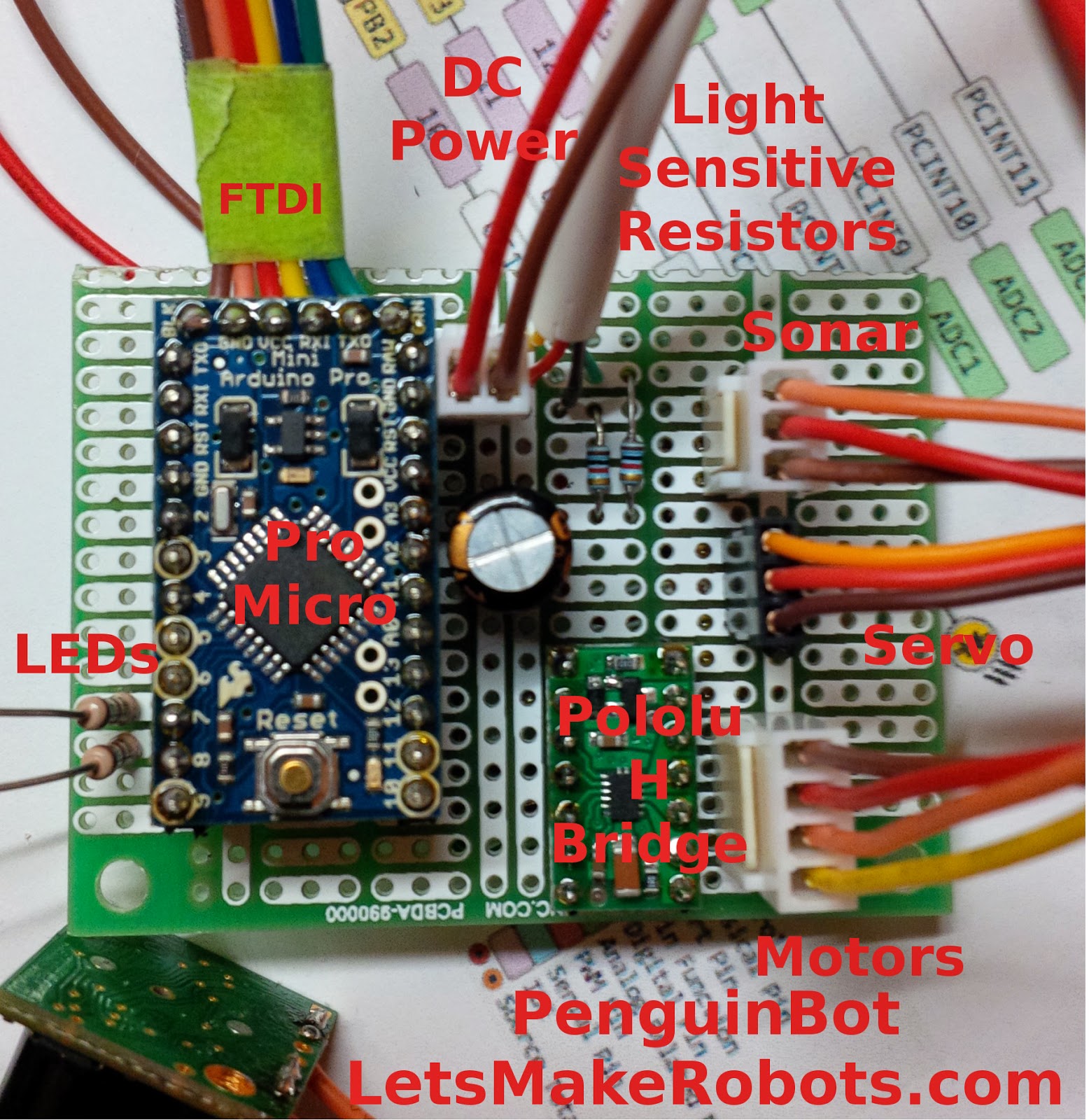
I will use an Arduino Pro Mini to run this Bot, the motors will be managed through a Polulu DRV883 H-bridge.


For obstacle avoidance, I will be using a MaxSonar EZ1. A *lot* of overkill, and way too expensive for this project, but... It's what I've got in the parts bin.
Two Light Sensitive resistors should allow it to waddle towards a light, or follow my children with a flashlight.
A small microphone will allow it to react to sound.
A micro servo to rock the body back and forth.
And a few strategically placed leds just for fun...

I guess I'll just call this board "Bird Brain"!


Wish me luck!

Update: 4:30pm Sunday afternoon


Electronics and most of the mechanical is done.  90% of the coding is complete as well....

My challenge to myself was to start from scratch at 6pm Friday night, and with a house full of kids, (my 7 year old son had two other boys over as well) and the wife gone for the weekend, complete this project by midnight tonight.

I actually believe I'm on track.

Update: 8:00pm  Sunday night.  4 hours to go, and I've got it reassembled and the "skin" back on.  Just some mild "glitches" in the code, and we should have another video up before midnight... (unless the wife gets home before then?)


Update: 10:00pm  Sunday night. 

Ok, I'm exhausted.  I've been at this hack for over 60hrs... Sleep calls... I can no longer see...

For what it's worth, the code to this point is here:
https://github.com/michaeljball/PenguinBot

I will finish it tomorrow...
Cheers.


References:
Pololu: DRV8835 Dual Motor Driver Carrier
Texas Instruments: DRV8835 Dual Low Voltage H-Bridge
Instructables: Arduino Motor Shield V3
MAXBOTIX: LV-MaxSonar®-EZ1
Arduino light seeker
Arduino powered Braitenberg vehicle
Light chaser
Servo Problems With Arduino - Part 1
Get on the BlinkM Bus with a BlinkM Cylon