Search This Blog

Showing posts with label robot. Show all posts

Wednesday, 21 May 2014

Dancing Brushbot assembly...

Update on the Dancing Brushbot: 


In my last posting, I mused about the potential of making this cheap wind-up toy actually move about...
possibly avoid obstacles...  

Well, I've had some time to think and plan, and dismember the cheerful little dude...


Here is the sum of his parts.

You'll  notice the little white box lower middle of the picture.  That is the spring wound mechanism that made him dance...


It fit inside the body, in an area roughly 2.5cm high by 1.5cm wide by 1cm deep.

The is the space I have for electronics...


 This is the underside of our friendly Hexbot Nano, with the battery removed. I'll be simply connecting to the positive and negative battery wires for this build.


Opened up, you can see the miniature "pager" motor with the offset weight that vibrates the Hexbot Nano.  
I've also placed the protection diode inside the body of the Hexbots, as there was no room on the main circuit board. 


  I then hotglued the Dancing bot's feet onto the tops of the Hexbot Nano's and drilled a hole to pass the motor wires through.

Here is the blank board in it's body casing. That's it.  That's all the room I have for electronics.


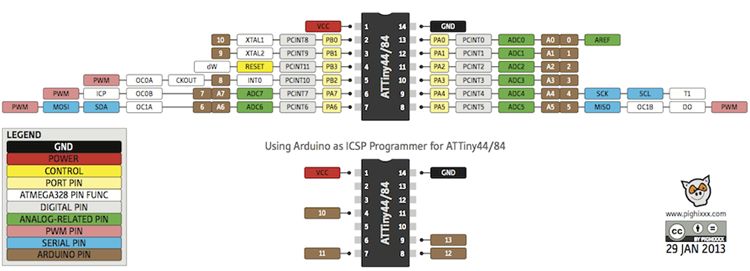
Luckily, an Attiny84 in socket, as well as a power connector and the ISP header all fit exactly on the board! I couldn't have asked for a better fit!

 The Sharp GP2Y0A21YK Infrared Distance Sensor is hotglued onto the stub that held the original Dancing bot's head, and the LiPo battery is velcroed onto the front of the body.
 Here, the ATtiny84 control board is placed into the body for sizing. 
Assembled, and ready to code.   I've placed the AA battery in the picture to demonstrate the size of this guy.


Watch this space over the next few days, as I get this guy up and dancing... 

(currently having problems with balance/center of gravity... this too will be conquered)


References:

Programming an ATtiny w/ Arduino 1.0
LetsMakeRobots: Mogul - Program standalone ATtiny / ATmega chips through an Arduino
LetsMakeRobots: Ladvien - Robot Metallurgy 101 -- AVR Lesson Journal
LetsMakeRobots: attiny85 h-bridge ldr robot
LetsMakeRobots: Lumi - TinySpider
http://www.iheartrobotics.com/2009/12/upgrade-led-hexbug-hack.html


Friday, 16 May 2014

Upcoming fun project with dual Brushbot and ATtiny84...

While I'm waiting on parts (extruder, beated bed,  and hotend) for my RepScrap 3D printer, I thought I would have a bit more fun...

Someone sent me this hilarious video, and it started me thinking...

I frequently attend various  vendor trade shows,  and invariably, the vendors hand out useless trinkets as advertising...  I usually do one of three things with these... 

    1) anything electronic gets tossed into the parts bin, 
    2) anything of a "toy" nature goes to my children (yes, I got that order straight) 
    3) everything else gets tossed them into the garbage.


 So I happen to have a pair of these "electronic devices" in my parts bin.  I think they are commercially known as "Hexbot Nanos

They would effectively replace the toothbrush head and pager motor in the above video....

But I also received one of these little wind up distractions to the left here...  

Mechanical spring wound clockworks makes him do a little dance...  

For some strange reason, he hadn't quite made it to the kids yet...  hmmm....


It looks like those Hexbots might just fit the bottom of his feet..... 

Maybe I could run them directly from an ATtiny84 as in THIS blog... 
yes, I know I should add a transistor to drive each motor, but when I looked up the current draw on a free running pager motor, low and behold they are around 20-40ma... well within the range of the ATtiny84 pins capability.


 Current and RPM specs:

Voltage RPM Current (free) Current (stall)
1.5V 9700 17.5mA 120mA
3.0V 18420 22mA 260mA
5.0V 31900 32.1mA 420mA


Add a Sharp IR proximity sensor onto his chest, a small LiPo battery on his back for balance, the gratuitous leds on the head, and I think we just may have ourselves the next project.... It doesn't get much simpler...

(ok, ok... yes, I'll likely wire in a connector for the AVR programmer... but that's it...  well... and maybe find another pager motor to replace the spring wound mechanism that makes him dance... but THATs it... really...

maybe...)


I thought I would put this picture in, just to show the scale... 


References and prior art:


Tuesday, 22 April 2014

Introducing an Arduino Finite State Machine library to PenguinBot

First off... PenguinBot was featured on Hackaday last Friday!  Yay!


I spent a little time yesterday reworking my code for PenguinBot to replace the homemade state machine of  If/then/else and switch statements, with a proper State Machine Library.

I specifically chose the SMLib  State Machine Library because of it's simplicity and lack of overhead.   I know there are other full featured State Machine Libraries out there, but this one serves the purpose well. 

After all..  it's just a penguin that avoids obstacles...  most of the time... more or less... 

This library allows you to have a Head and Body for each state.  
The "Head" is for initializing variables each time you transition into the state.  The "Body" contains the actions that are to take place each time you loop through the state,such as incrementing a counter, or checking a sensor.


Regardless of whether you are in "Manual Mode", "Object Avoidance Mode", or the yet to be implemented "Light Following Mode",  State Machine "m1" controls motion. 
The states are as follows:
1 = Stopped
2 = Forward
3 = Avoiding Obstacle
4 = Turn Left
5 = Turn Right
6 = Reverse
The Global Variable "MotionStop" dictates how much time is spend in any state.


Current (imperfect) code here:


Setup and Initialization of the State Machine :
/************************************************************************/
#include <SM.h>
SM m1(m1s1h, m1s1b);  //Initialize state machine m1 with head and body

setup(){
// There is nothing in setup related to SMLib
}

//  Typical events to manage an Autonomous Robot in the main loop
void loop() {
  get_sensors(); // Read all sensors, like proximity, etc...
  EXEC(m1); // Execute the State Machine
  provide_feedback(); // Send status updates via Serial
  get_serial(); // Grab commands from Serial
}
/**************************************************************************/


This is the FSM.ino module:
/**********************************************************************/
State machine m1 is for motion control
the states are as follows:
1 = Stopped
2 = Forward
3 = Avoiding Obstacle
4 = Turn Left
5 = Turn Right
6 = Reverse
MotionStop dictates how much time is spend in any state.
*/

State m1s1h(){ // m1s1 is --- Motion:Stopped
  Serial.println("Motion:Stopped (State 1)");
  halt();
}//m1s1h()

State m1s1b(){
  if(m1.Timeout(5000)){ // Maximum 5 seconds idle time
    m1.Set(m1s2h, m1s2b);
    Serial.println("changing to Motion:Forward (State 2)");
  };
}//m1s1b()

State m1s2h(){ // m1s1 is --- Moving Forward
  Serial.println("Motion: Forward (State 2)");
}//m1s2h()

State m1s2b(){
  if(m1.Timeout(MotionStop)){ // Maximum 5 seconds forward motion
    m1.Set(m1s1h, m1s1b);
    Serial.println("changing back to Motion:Stopped (State 1)");
  }
  
  if(Distance > MINDIST){
   BlinkM_fadeToRGB( blinkm_addr, 0,255,0 ); // Display GREEN Status
   forward();
  } else {
    Serial.println("changing to Motion:Avoid Obstacle (State 3)");
    m1.Set(m1s3h, m1s3b);
  }
}//m1s2b()

State m1s3h(){ // m1s3 is --- Avoid Obstacle
  Serial.println("Motion: Avoid Obstacle (State 3)");
  MotionStop = 200; // Set turn time for Obstacle Avoidance
  BlinkM_fadeToRGB( blinkm_addr, 255,0,0 ); // Display Warning RED

}//m1s3h()

State m1s3b(){
  if(DistLeft > DistRight){
    m1.Set(m1s4h, m1s4b); // Change State to Left Turn
  } else if(DistRight > DistLeft){
    m1.Set(m1s5h, m1s5b); // Change State to Right Turn
  } else {
    Serial.println("changing back to Motion:Stopped (State 1)");
    m1.Set(m1s1h, m1s1b);
  }
}//m1s3b()


State m1s4h(){ // m1s1 is --- Turning Left
  Serial.println("Motion: Left Turn (State 4)");
}//m1s4h()

State m1s4b(){
  if(m1.Timeout(MotionStop)){ // Maximum 5 seconds forward motion
    m1.Set(m1s1h, m1s1b);
    Serial.println("changing back to Motion:Stopped (State 1)");
  }
   BlinkM_fadeToRGB( blinkm_addr, 0,255,0 ); // Display GREEN Status
   left();
}//m1s4b()


State m1s5h(){ // m1s1 is --- Turning Right
  Serial.println("Motion: Right Turn (State 5)");
}//m1s5h()

State m1s5b(){
  if(m1.Timeout(MotionStop)){ // Maximum 5 seconds forward motion
    m1.Set(m1s1h, m1s1b);
    Serial.println("changing back to Motion:Stopped (State 1)");
  }
   BlinkM_fadeToRGB( blinkm_addr, 0,255,0 ); // Display GREEN Status
   right();
}//m1s5b()


State m1s6h(){ // m1s1 is --- Reverse
  Serial.println("Motion: Reversing (State 6)");
}//m1s6h()

State m1s6b(){
  if(m1.Timeout(MotionStop)){ // Maximum 5 seconds forward motion
    m1.Set(m1s1h, m1s1b);
    Serial.println("changing back to Motion:Stopped (State 1)");
  }
   BlinkM_fadeToRGB( blinkm_addr, 0,255,0 ); // Display GREEN Status
   reverse();
}//m1s6b()

/************************************************************************/


MotionStop duration is typically set either as a Serial Command parameter when in Manual Mode, or predetermined time lapse for "In Motion" or "Idle"  when in Autonomous Mode (Either Obstacle Avoidance or Light Following).

The exception to this, is in State 3 --- Avoid Obstacle.  In this state, it has been determined that an obstacle blocks the way ahead, and an assessment is done as to whether there is more room to the left or to the right.   "MotionStop" duration is set up to allow just enough time to turn the bot roughly 90 degrees. "MotionStop = 200; // Set turn time for Obstacle Avoidance"


Over the next few days, I will convert the rest of the code to use this library, and show the "Light Following Mode"


References:
Arduino-Pi: Of Finite State Machines and Robotics
https://github.com/michaeljball/PenguinBot

Arduino Playground: A novel and relaxed view on finite state machines
http://playground.arduino.cc/Code/FiniteStateMachine
Robot Virtual Worlds – Maze Crawler
Embedded Micro:  basic FSM to control a very simple robot.
http://www.mathertel.de/Arduino/FiniteStateMachine.aspx
http://hacking.majenko.co.uk/finite-state-machine


Tuesday, 15 April 2014

Quick Update on PenguinBot


I've moved the MaxSonar EZ1 onto a panning servo, and attached it to the outside of the electronics enclosure.


I've also added a "BlinkM"  intelligent LED to give PenguinBot some personality.  I haven't written the code for it yet, so it's currently just scanning through it's default pattern... but there's always tonight....

I've added Serial Control to drive it tethered via USB, my expectation is that I will get a BlueTooth-FTDI  adapter...

I've broken the Arduino code out into separate tabs according to their role, ie: motion control, serial interface, sound...


This project is growing legs.....


References:

BlinkM datasheet


Saturday, 12 April 2014

PenguinBot - Fun weekend Arduino Project!


This video is right after placing the covering back on, and powering it up.  I have not fixed a bug in the object avoidance yet, so you will hear the motors running full steam backward to get away from the phantom obstacle.    I really wanted to post this just to show how obnoxious the sound from the preserved toy is!

********************************************************************************


After seeing the Awesome Hurby Bot, I thought I would have a bit of fun.

My wife is out for the weekend, lets see what I can conjure up!
I started with (very noisy) Penguin toy that has not worked in a year or so. We left the batteries in it, and they leaked all over the inside, corroding the leads to the motor... Hmmm... fix it as is? Or make it AWESOME!!!


So, of course I chose AWESOME!
I expect this build to take a day, with some code tinkering over the next week.
So what do we have to start with, and what can we add?


The penguin toy itself had an odd combination of two wheels at 90 degree angles to each other. These would alternately spin causing a very strange walking pattern. It also had an offset gear rocking a lever inside, with a plastic ball attached to the top of the penguin body with velcro.

While walking the penguin would rock back and forth, screeching, as penguins do. (I want to preserve this motion.)


So, first thing to do was find two SMALL DC gear motors to provide proportional steering. A trip to the dollar store, and I had what I wanted. A pair of cheap locomotive engines with 3v DC gear motors!


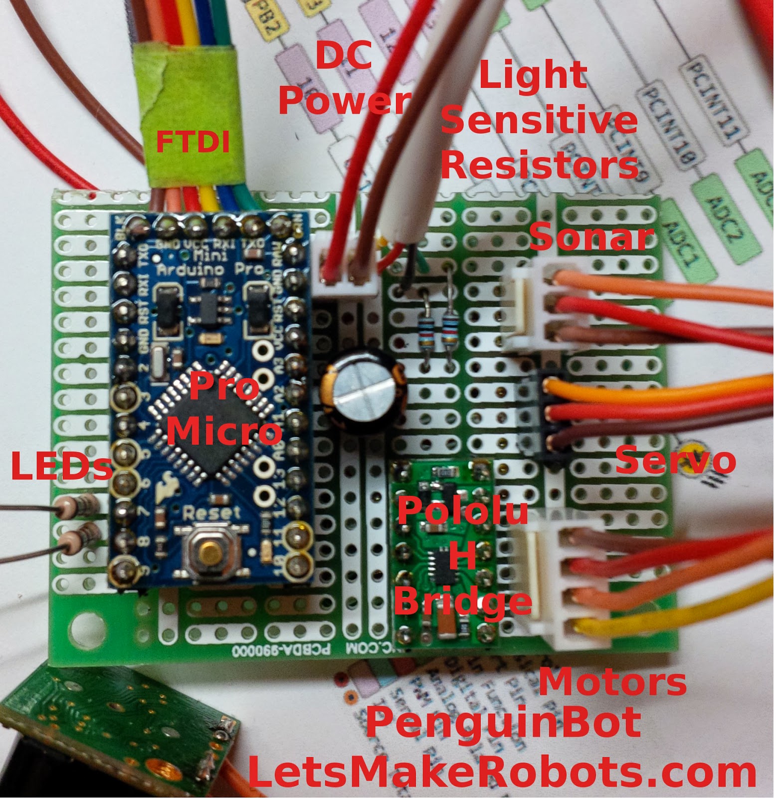
I will use an Arduino Pro Mini to run this Bot, the motors will be managed through a Polulu DRV883 H-bridge.


For obstacle avoidance, I will be using a MaxSonar EZ1. A *lot* of overkill, and way too expensive for this project, but... It's what I've got in the parts bin.
Two Light Sensitive resistors should allow it to waddle towards a light, or follow my children with a flashlight.
A small microphone will allow it to react to sound.
A micro servo to rock the body back and forth.
And a few strategically placed leds just for fun...

I guess I'll just call this board "Bird Brain"!


Wish me luck!

Update: 4:30pm Sunday afternoon


Electronics and most of the mechanical is done.  90% of the coding is complete as well....

My challenge to myself was to start from scratch at 6pm Friday night, and with a house full of kids, (my 7 year old son had two other boys over as well) and the wife gone for the weekend, complete this project by midnight tonight.

I actually believe I'm on track.

Update: 8:00pm  Sunday night.  4 hours to go, and I've got it reassembled and the "skin" back on.  Just some mild "glitches" in the code, and we should have another video up before midnight... (unless the wife gets home before then?)


Update: 10:00pm  Sunday night. 

Ok, I'm exhausted.  I've been at this hack for over 60hrs... Sleep calls... I can no longer see...

For what it's worth, the code to this point is here:
https://github.com/michaeljball/PenguinBot

I will finish it tomorrow...
Cheers.


References:
Pololu: DRV8835 Dual Motor Driver Carrier
Texas Instruments: DRV8835 Dual Low Voltage H-Bridge
Instructables: Arduino Motor Shield V3
MAXBOTIX: LV-MaxSonar®-EZ1
Arduino light seeker
Arduino powered Braitenberg vehicle
Light chaser
Servo Problems With Arduino - Part 1
Get on the BlinkM Bus with a BlinkM Cylon


Thursday, 10 April 2014

Controlling a Raspberry Pi / Arduino Bot from the Internet Part 3 of 3

This is part three of a three part Series to explain how I control my BotTwo semi-Autonomous Robot from a webpage on the Internet. 

In Part One, we talked about the Interaction and Communications between the end user device (laptop/tablet/phone), the Web Server presenting the control panel, and the socket service listening for commands on the Robot itself.

In Part Two, we discussed how to use python on the Raspberry Pi to initialise a tcp socket listener for incoming commands from the Web ServerWe took the incoming message, and repeated it via I2C to the Arduino that is managing the DC motors and wheel encoders.


Raspberry Pi Arduino I2C
Raspberry Pi / Arduino I2C

In this, the third and final instalment, we will discuss the pieces of code used on the arduino to receive the commands via I2C, format and process them, and send a status back to the Raspberry Pi consisting of Motion status, Left Encoder count, Right Encoder count, and current Speed.

As mentioned in the previous article, I am treating the I2C as a fast serial interface, and as such send a formatted, comma separated string to the Arduino consisting of a command character, a comma, a parameter, and a line termination. 

For example:   'f',200 \n\r    would indicate  "Go Forward 200mm"

I'm going to have to assume that you know something about Arduino if you've made it this far in the conversation, so I'm not going to lay out the entire code here, simple the parts that fulfill the I2C and serial communications, command processing, and status reporting.

There is an excellent article from Oddbot on LetsMakeRobots describing how to control motor speed through PID with an Arduino here: http://letsmakerobots.com/node/38636
  
I personally am using the Arduino Motor Shield V3, there is great documentation in Arduino Playground, and there is a very good Instructable on it


So, without further ado... lets get into our code!


For the Arduino slave, you need to set up a few defines:
#define SLAVE_ADDRESS 0x33      // I2C slave address
#define  REG_MAP_SIZE    32     // Max I2C Buffer size
#define  MAX_SENT_BYTES  7      // Command, parameter, heading, batt 
#define  IDENTIFICATION  0x0D   // An identifier for this slave
Then we include the Wire library.
#include <Wire.h>         // Include the Wire library so we can use I2C. 

Set up some variables for communications:
String Command = "";                  // The parsed Command from the RPi
String Parameter = "";                // The parsed Parameter from the RPi

char inData[REG_MAP_SIZE];            // Raw Buffer for the incoming serial data
char *inParse[REG_MAP_SIZE];          // Buffer for the parsed data chunks

char I2CinBuffer[REG_MAP_SIZE];       // Raw Buffer for the incoming I2C data
byte I2CoutBuffer[REG_MAP_SIZE];      // Buffer for the outgoing I2C data

String inString = "";                 // Storage for data as string
int index = 0;

boolean stringComplete = false;    // Tells the main loop that it has received
                                   // a command via the Serial port

boolean I2CComplete = false;       // Tells the main loop that it has received
                                   // a command via I2C  
In setup() we initialize Serial and Wire:
Serial.begin(115200);

Serial.println("RST, Running Motors_I2C_01. 140328");

Wire.begin(SLAVE_ADDRESS);       Serial.println("I2C Initiated.");

Wire.onRequest(requestEvent);     // Set up Request Interrupt Service Routine
Wire.onReceive(receiveEvent);     // Set up Receive Interrupt Service Routine

I2CoutBuffer[0x08] = IDENTIFICATION; // ID register

Serial.println("########## LET US BEGIN #############");

In loop()  you need to watch for Serial or I2C commands available:
SerialEvent();                        // Grab characters from Serial

if (stringComplete)                // if there's any serial available, read it: 
{ 
      ParseSerialData();            // Parse the recieved data 
      inString = "";                   // Reset inString to empty 
      stringComplete = false;   // Reset the system for further input of data
}


if (I2CComplete)                 // if  I2C commands are available, read it: 
{ 
      ParseI2CData();           // Parse the recieved data 
      inString = "";               // Reset inString to empty 
      I2CComplete = false;   // Reset the system for further input of data
}
Then there are Serial Receive and I2C Request and Receive handlers:

void SerialEvent() 
{
  while (Serial.available() && stringComplete == false)    // Read while we have data
  {
    char inChar = Serial.read();             // Read a character
    inData[index] = inChar;                  // Store it in char array
    index++;                                 // Increment where to write next  
    inString += inChar;                      // Also add it to string storage 
    
    if (inChar == '\n' || inChar == '\r')    // Check for termination character
    {
      index = 0;
      stringComplete = true;
    }
  }
}


void receiveEvent(int howMany) {
  int readCount = Wire.readBytes(I2CinBuffer, howMany);
  I2CinBuffer[readCount] = 0;
  I2CComplete = true;
}


void requestEvent()
{
     Wire.write(I2CoutBuffer, 8); 
     lcount = 0;  rcount = 0;          // reset left and right tick counters
 
}

// storeData is used to copy volatile variables into a register for I2C send
void storeData()
{
     cli();
     I2CoutBuffer[0x00] = highByte(motion);   // Notice Highbyte/Lowbyte order  MSB,LSB
     I2CoutBuffer[0x01] = lowByte(motion);
     I2CoutBuffer[0x02] = highByte(lcount);
     I2CoutBuffer[0x03] = lowByte(lcount);
     I2CoutBuffer[0x04] = highByte(rcount);
     I2CoutBuffer[0x05] = lowByte(rcount);
     I2CoutBuffer[0x06] = highByte(spd);
     I2CoutBuffer[0x07] = lowByte(spd);
     I2CoutBuffer[0x08] = IDENTIFICATION;
     sei();

}
Once the Command and Parameters are received they have to be parsed into functions to control the Autonomous Rover:
// Take the Comma separated Serial string and format it to Command and Parametervoid ParseSerialData()
{
  char *p = inData;                // The data to be parsed
  char *str;                       // Temp store for each data chunk
  int count = 0;                   // Id ref for each chunk
    
  while ((str = strtok_r(p, ",", &p)) != NULL)  // seperate  at each "," delimiter   
  { 
    inParse[count] = str;      // Add chunk to array  
    count++;      
  }

  if(count == 2)     // If the data has two values then..  
  {
    Command = inParse[0];       // Define value 1 as a Command identifier
    Serial.print("Command from Serial in is.... "); Serial.println(Command);
    Parameter = inParse[1];     // Define value 2 as a Parameter value
    Serial.print("Parameter from Serial in is.... "); Serial.println(Parameter);

    processCommand();
  }
}
 
// Take the Comma separated I2C string and format it to Command and Parameter
void ParseI2CData()
{

  char *p = I2CinBuffer;                // The data to be parsed
  char *str;                       // Temp store for each data chunk
  int count = 0;                   // Id ref for each chunk
    
  while ((str = strtok_r(p, ",", &p)) != NULL)    // seperate at each "," delimiter
  { 
    inParse[count] = str;      // Add chunk to array  
    count++;      
  }
  //  Serial.print(I2CinBuffer); Serial.print("  "); Serial.println(count);

  if(count == 2)     // If the data has two values then..  
  {
    Command = inParse[0];       // Define value 1 as a Command identifier
    Serial.print("Command from I2C in is.... "); Serial.println(Command);
    Parameter = inParse[1];     // Define value 2 as a Parameter value
    Serial.print("Parameter from I2C in is.... "); Serial.println(Parameter);
    
    processCommand();
  }
}

//  Determine actions from Command / Parameter  -- This can be called from either 
//  Serial or I2C parser   
void processCommand()
{
char buf[REG_MAP_SIZE]; // make this at least big enough for the whole string
    Parameter.toCharArray(buf, sizeof(buf));    // Convert String to Character array  

    Serial.print("CMD,"); Serial.print(Command); Serial.print(","); 
    Serial.print(Parameter); Serial.print(","); Serial.println(now);

    digitalWrite(rmbrkpin,LOW); digitalWrite(lmbrkpin,LOW);    // remove brakes
  
    // Call the relevant identified Command 
    if(Command[1])  Command[0]=Command[1];  
    switch(Command[0])
    {
      case 'f':                           // Move Forward "Parameter" ticks
        lspeed = spd;   rspeed = spd;
        ldir = forward; rdir = forward;
        MotionStop = atoi(buf);

        motion = MOVE_FORWARD;
        TargetHeading = CurrentHeading;
        turning = 0; 
      break;

       case 'b': 
        lspeed = spd;    rspeed = spd;
        ldir = backward; rdir = backward;
        MotionStop = atoi(buf);
        motion = MOVE_BACKWARD;
        TargetHeading = CurrentHeading;
        turning = 0;      
        break;

       case 'r': 
        lspeed = spd;    rspeed = spd;
        ldir = forward; rdir = backward;
        MotionStop = atoi(buf);
        motion = TURN_RIGHT;                 
         motion = IN_MOTION;      turning = 1;     
        break;

       case 'l': 
        lspeed = spd;    rspeed = spd;
        ldir = backward; rdir = forward;
        MotionStop = atoi(buf);
        motion = TURN_LEFT;
        motion = IN_MOTION;   turning = 1;     
        break;

       case 's':                                         // Set Desired Speed
         spd = atoi(buf);
        break;
        
     case 'x':                                             // STOP!!!
       lspeed = 0;   rspeed = 0;
       MotionStop = 0;
       motion = STOP;
       digitalWrite(rmbrkpin,HIGH); digitalWrite(lmbrkpin,HIGH);    // Apply brakes
       lcount = 0; rcount = 0;        // reset left and right tick counters
        break;
        
    }  
     digitalWrite(rmbrkpin,LOW); digitalWrite(lmbrkpin,LOW);    // release brakes  
}


I will post the complete code up on my github in the next day or so.

Please let me know if I need to clarify anything...
 

References:

http://dsscircuits.com/index.php/articles/78-arduino-i2c-slave-guide
http://gammon.com.au/i2c
Adafruit: Configuring the Pi for I2C
http://blog.oscarliang.net/raspberry-pi-arduino-connected-i2c/