Search This Blog

Monday 29 December 2014

Prototype Printer Controller Cont'd - Teensy 3.1 w/DC motor/encoders


Here's some more shots of the controller prototype..

I've added a DC/DC converter for clean 5v power to the electronics (5amp).  I've also added a separate 5v linear regulator for the Extruder stepper circuitry.
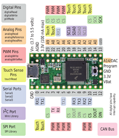
To get access to the extra pins on the bottom of the teensy, I used a dual row header, and bent the inside pins at a 90 degree angle, trimmed, and soldered.
The shot on the right shows the Real Time Clock crystal soldered into place.

And of course I use my 
legacy 3D extruder 
religiously to lay down layers of plastic "wire holders". 


This is where I wish I had kept all of my old wire wrap tools... Who knew I'd pick up electronics again after almost a 20 year hiatus.

Anyway, power and ground... check. 

Now to the rest of the wires..
 

Sunday 28 December 2014

Prototype Board: DC motor/Encoder - Teensy 3.1 based 3D printer controller

This will be a short post today.  

I had mentioned putting up pictures as I go along, so I took this to show the first prototype of the controller board.

Here is the layout of my Teensy 3.1 based 3D printer controller.


As of this shot, I have not yet wired it.  Nor have I installed the analog components (power supply, heater drivers, pullup resistors, filter capacitors, etc...).  It is also missing the connector for the extruder stepper motor. 

As I described in my previous post, my motor control design is based on Adafruit's Motor Shield V2.3.  For my prototype... well... I'm using their shield, pilfered from one of my older robots. This fantastic design employs an NXP PCA9865 16 channel 12 bit PWM controller, intended to drive LEDs, but instead to  driving a pair of dual Mosfet H bridge TB6612FNG motor drivers.

The Library for this Shield works with the Teensy 3.1 just fine. (It is just I2C after all).

Ok... I'm off to wire this up... wish me luck.


Thursday 18 December 2014

Teensy 3.1 Repstrap printer with DC motor control and Flex Timer Quadrature Encoders


As I re-engage my 3D Repscrap printer project,  I have decided to replace the two 8bit AVR based  Arduino pro minis running at 16Mhz with a single  Teensy 3.132bit ARM core M0 based board running at 96Mhz.   The Teensy is significantly faster, more powerful, and still only $20USD.


I was considerably influenced to change my direction based on this incredibly detailed Blog over at Freescale Nikki  Verriddagari, a Freescale developer, managed to replace the typical Arduino Mega2560 seen in most Reprap style printers with the Teensy 3.1 inside of 3-4 weeks, as a side project.

Both the Teensy and Reprap communities rallied to assist Nikki through a few difficult spots, and huge kudos to the developer of the Teensy 3.1, Paul Stoffregen, for working on the Teacup code with Nikki and getting it debugged and working!


The Freescale MK20DX256VLH7 processor used on the Teensy has two hardware based Quadrature Decoder modules built in. There is a good appnote on how to use them at Freescale. 
"The FlexTimer is a complex, general-purpose timer module that also possesses special features dedicated to a motor control application"

While perusing the Teensy 3.1 developer's site, I came across a forum article where Trudy Benjamin had created a library to use these FTM to read two quadrature encoders.   This looked like as good as anything for a starting point.


I'm using her QuadDecode library for the X and Y axis, and have decided to manage both Z-Axis encoders through hardware interrupts. My thoughts being that the Z-Axis travel is both minimal and predictable. I believe (I've been wrong before!) that Z-Axis movement is conducted typically after a horizontal layer of X/Y is completed.  However!!!  This does not preclude error correction in the Z-Axis PIDs. If something were to bump the extruder or a collision occurred that caused the Z-Axis to change, the PID would try to correct, and the interrupts must be responsive enough to handle this. Running at 96Mhz, I'm confident enough to give this a good shot.

My Design Concept:

I'm basing my requirements loosely on the RAMPS/Mega design, but for DC motors and quadrature encoders.

There will be four DC motors:  One each for the X and Y axis, and two for the Z axis. All will have inexpensive DC brushed motors.  The X and Y axis will have linear optical encoders, while the Z axis will have rotary optical encoders. (This is a mechanical decision for MY implementation, the electronics and firmware should not care).  All motor/encoder pairs will have endstops at each end of their travel.

To manage PWM for four DC motors, as well as PWM for the Extruder heater, Bed heater, and fans, I am choosing to borrow a design from Adafruit's Motor Shield V2.3.  In this shield, they employ a PCA9865 I2C 12 bit PWM controller, driving a pair of dual Mosfet H bridge TB6612FNG motor drivers.


A standard Pololu stepper motor driver board will be used to manage the extruder.

Primary communications will be via the Teensy's USB Serial interface, however I am including a uSD card reader for future plans to read G-Code directly from uSD card.


Starting with the example pinout used in the QuadDecode library,   I have drafted up a connectivity chart and initial schematic that I will be wiring up over the next few days.


Teensy 3.1 Based 3D printer with DC motor/Quad Encoders

Next blog will include photos of the build.


Please feel free to provide constructive criticism as I journey down this path.


References:
PJRC Forum: Hardware Quadrature Code for Teensy 3.x  
PJRC: Teensy 3.1 Encoder Library
Freescale: Configuring the FlexTimer for Position and Speed Measurement with an Encoder
Freescale: PMSM Vector Control with Quadrature Encoder on Kinetis
Kinetis: K20 Sub-Family Reference Manual 
Data sheet: Supports: MK20DX64VLH7, MK20DX128VLH7, MK20DX256VLH7 
Teensy 3.1: Pulse Width Modulation 
Loglow: Interval Timer Library for Teensy 
PJRC: New I2C library for Teensy3  
PJRC: Connecting headers to those pins on the bottom of the Teensy 3.1 


Thursday 4 December 2014

Should I port SLAM to the Raspberry Pi's unused GPU on my Autonomous Rover?


Right now, I use Arduinos for motor control (PID control for encoders and dc motor) as well as aggregating sensor data and feeding the Raspberry Pi on my Autonomous Rover.

The Pi runs a live stream webcam for the rover, manages the webpage control console, and maps the environment for dead reckoning navigation.  This is a lot of work for one little CPU.

I've recently seen a few articles on using the dormant GPU on the Pi. and though that Simultaneous Localization and Mapping (SLAM) would be perfectly suited for the GPU's capabilities. Real world mapping and localization should be practically identical to Video Game based algorithms... It's been almost a year since Broadcom opened up the specs for this chip.

I would also use the GPU for calculating shortest path via A* routines. 

So... has anyone looked into this? 
 (And yes... I "Googled" it first...)


References:

Andrew Holme: Accelerating Fourier transforms using the GPU
Pete Warden: How to optimize Raspberry Pi code using its GPU
GPGPU hacking on the Pi
Hacking The GPU For Fun And Profit (Pt. 1) 
Broadcom released the specs for the VideoCore IV GPU
SLAM: Remotely-Processed Visual SLAM Using Open-Source Software 


Thursday 21 August 2014

Running Kinetis Design Studio (32bit Eclipse) on 64bit Ubuntu


YAY!!!!  I got it working!  

Back in the end of May, I enrolled in the beta for Kinetis Design Studio installer for Linux to allow me to develop on my Teensy 3.1 bare-metal,
only to find that it would not run on my Ubuntu 14.04 64bit.  I'm running Oracle Java 7


Kinetis Design Studio installed properly from DEB, but when I launched it, it immediately complained that it could not load the SWT library for Eclipse.  It turns out that they built the Debian (Ubuntu) base on 32bit Eclipse.  

After some futzing around, I opened a case with Freescale Support: (putting the details here for search engine assistance)
SR Number: 1-2152355207Date Opened: 07/28/2014 05:28:35 PHX timeSubject: kinetis-design-studio will not load in Ubuntu 14.04Description: Fresh install of Ubuntu 14.04uname -aLinux ballmik-Satellite-L305 3.13.0-32-generic #57-Ubuntu SMP Tue Jul 15 03:51:08 UTC 2014 x86_64 x86_64 x86_64 GNU/Linux

Running Oracle Java java version "1.7.0_65"Java(TM) SE Runtime Environment (build 1.7.0_65-b17)Java HotSpot(TM) 64-Bit Server VM (build 24.65-b04, mixed mode)

Eclipse appears to be built for 32bit platform. is the a 64bit version ?attaching eclipse log.
Thank you.
!ENTRY org.eclipse.osgi 4 0 2014-07-28 08:06:23.472!MESSAGE Application error!STACK 1java.lang.UnsatisfiedLinkError: Could not load SWT library. Reasons: /home/ballmik/.eclipse/org.eclipse.platform_4.3.2_870091379_linux_gtk_x86/configuration/org.eclipse.osgi/bundles/430/1/.cp/libswt-pi-gtk-4335.so: libgtk-x11-2.0.so.0: cannot open shared object file: No such file or directoryno swt-pi-gtk in java.library.path/home/ballmik/.swt/lib/linux/x86/libswt-pi-gtk-4335.so: libgtk-x11-2.0.so.0: cannot open shared object file: No such file or directoryCan't load library: /home/ballmik/.swt/lib/linux/x86/libswt-pi-gtk.so


Their quick response was that the DEB was built on/for Ubuntu 12.04LTS 32bit.... 

Not helpful...  So...  life got in the way, and I finally returned to this last night.  With fresh eyes, I simply searched G00gle for "running 32 bit eclipse on 64 bit Ubuntu 14.04"  and came up with a bunch of different solutions. 


The issue is that in 64bit Ubuntu base install, the 32bit libraries are not installed.  period.

Prior to Ubuntu 14.04, you used to be able to "sudu apt-get install ia32-libs", but they removed this ability recently because dpkg now has multi-arch enabled by default. MEANING, that if you actually knew what libraries were failing, you could reinstall them with a :i386 at the end of the package name.  Seemed like a lot of work to find the specific libraries... 


Here's what worked for me.
(from Stackoverflow: How to install ia32-libs in ubuntu 14.04 LTS)

sudo -i
cd /etc/apt/sources.list.d
echo "deb http://old-releases.ubuntu.com/ubuntu/ raring main restricted universe multiverse" >ia32-libs-raring.list
apt-get update
apt-get install ia32-libs


Reboot, and voila! Kinetis Design Studio is now working!


Now, on to figuring out how to code for the Teensy 3.1...


Resources:

Freescale: Kinetis Design Studio
Ubuntu.com: Multiarch
Stackoverflow: How to install ia32-libs in ubuntu 14.04 LTS
Teensy 3.1 Bare-Metal


Tuesday 15 July 2014

Developing a Robot Shield for Teensy 3.1: Looking for feedback

The many features and beautiful simplicity of the venerable Arduino, have captured the minds and imaginations millions of hobbyists, programmers, and Roboteers.  

Arduino, as a company, has created a diverse number of boards as Open Source Hardware . This diversity caters to various physical, electrical, and I/O requirements, allowing for a broad spectrum of applications.   That said, an entire industry has sprung up around reproducing variants of the Arduino

All of these boards, however,  have two things in common.  
  1. They use Atmel AVR 8bit microcontrollers (Typically ATmega328 or in the case of the Mega - ATmega1280 or 2560)
  2. They have an Arduino bootloader installed to allow quick and convenient development/upload cycles with the Arduino IDE.


One of the most recent trends, has been to reproduce the Arduino form factor, complete with I/O, A/D and D/A for other microcontrollers, to allow them to utilize the hundreds (thousands?) of "shields" developed to support the Arduino family. 

Many of these alternative boards have also provided plug-ins (cross compilers and compatible libraries) for the Arduino IDE, to allow a smooth transition from the comfort of developing for the Arduino's 8bit AVR chip to a more complex 16 or 32bit microcontroller.


Today, I'm going to discuss the   Teensy 3.1.  

https://www.pjrc.com/teensy/teensy31.html 

Although not pin compatible with the Arduino family, it does leverage the Arduino IDE through Teesyduino for quick application development, while hopefully grooming it's users to step into more robust ARM development tools.  If UNO form factor compatibility is a requirement (for instance to use an existing shield) then the Teensy Development board from PetitStudio will do the trick.


The Teensy 3.1 is based on the   Freescale K20P64M72SF1 ARM Cortex M4 processor. It runs at 96Mhz, has 256K flash, and 64k RAM, 43 digital I/O, 21 Analog inputs, 12 PWM outputs,  12 Timers, 2 I2C ports, and 4 Serial UARTS.  Whew...

In addition to that, there are two TRUE Analog to Digital Converters that can be read simultaneously ie: no multiplexing inputs. Currently, Pedvide's ADC library can be used to access both ADCs. Thanks to Freescale, there is also a CAN Bus
(Controller Area Network - communication channel used in automobiles) Libraries for this will be available shortly.


Comparison Of Arduino UNO R3, Mega2560, and Teensy 3.1 specifications
Technical Specifications
Feature Arduino
Uno R3
Arduino Mega2560 Teensy 3.1 Units
Price 25 54 19.8 US Dollars
Processor Atmega328 ATMega2560 MK20DX256VLH7
Bits 8 8 32
    Core AVR AVR Cortex-M4
    Rated Speed 16 16 72 MHz
    Overclockable 24 24 96 MHz
Flash Memory 32 256 256 kbytes
    Bandwidth 16 16 192 Mbytes/sec
    Cache 0 0 256 Bytes
RAM 2 8 64 kbytes
EEPROM 1 4 2 kbytes
Direct Memory Access N/A N/A 16 Channels
Digital I/O 14 54 34 Pins
    Voltage Output 5 5 3.3V Volts
    Voltage Input 5 5 5V Tolerant Volts
Analog Input 6 16 21 Pins
    Converters 1 1 2
        Resolution 10 10 16 Bits
            Usable 10 10 13 Bits
        Prog Gain Amp 0 0 2
    Touch Sensing N/A 64 12 Pins
    Comparators 1 1 3
Analog Output 0 0 1 Pins
    DAC Resolution - - 12 Bits
Timers 3 6 Total 12 Total Pins
    FTM Type 0 0 3
        PWM Outputs 6 12 12
    PDB Type 0 0 1
    CMT (infrared) Type 0 0 1
    LPTMR Type 0 0 1
    PIT (interval) Type 1x8bit 2x16bit 2x8bit
 4x16bit
4
    Systick 0 0 1
    RTC (date/time) ** 0 1 1
Communication
    USB 1 1 1
    Serial 1 0 3
        With FIFOs 0 0 2
        High Res Baud 0 0 3
        Fast Clock 0 0 2
    SPI 1 1 1
        With FIFOs 0 0 1
    I2C 1 1 2
    CAN Bus 0 0 1
    I2S Audio 0 0 1
        FIFO Size 0 0 8


Now, if you've happened to get this far, here is the meat of this article:
There are few "shields" available for the Teensy as yet. There are a few adapters that provide UNO form factor, there is an audio shield, a TFT display shield, and a Smartmatrix shield, as well as a few other special use shields. 

What I am looking to develop, is a multifunction shield that maintains the small size of the teensy as much as possible, but incorporates a 9dof  like the LSM9DS0 Teensy 3.1 Micro Shield, as well as an l293d to drive two small DC motors. I2C, as well as Remaining I/O will be brought out to right angle headers on the edge of the shield.  

Before I complete the board design, I'm looking for feedback, motivation, and warnings (like "that l293 is going to get too hot!") ... 

 Cheers.


References:

https://www.pjrc.com/teensy/K20P64M72SF1.pdf
http://cache.freescale.com/files/32bit/doc/ref_manual/K20P64M50SF0RM.pdf 
http://cache.freescale.com/files/32bit/doc/quick_ref_guide/KQRUG.pdf


My Teensy Playlist on Youtube  


http://www.freescale.com/webapp/sps/site/prod_summary.jsp?code=K20_72
https://www.pjrc.com/teensy/td_libs_USBHostShield.html
OSH Park: SmartMatrix Shield for Teensy 3.1 
https://community.freescale.com/thread/320695 
http://hackaday.com/2013/12/09/meet-the-teensy-3-1/ 

http://trippylighting.com/category/uncategorized/
SmartMatrix Shield for Teensy 3.1
Adafruit 2.8" TFT Touch Shield for Arduino for Teensy 3.1
https://www.tindie.com/products/loglow/teensy-31-breakout/
http://petitstudio.blogspot.ca/2014/04/teensy-3-development-board-arduino.html
Audio Adapter Board for Teensy 3.0 & 3.1 and OctoWS2811 Adapter for Teensy 3.1 – Control tons of NeoPixels!
http://www.mccauslandcenter.sc.edu/CRNL/tools/oscilloscope
Github: KurtE- Modified version of Trossen Bioloid library to user Serialx objects
https://github.com/KurtE/Teensy3.1-Breakout-Boards
http://zentasrobots.com/
http://www.circuitsathome.com/category/mcu/arduino/usb-shield

http://forum.pjrc.com/threads/26017-Teensy-3-1-and-9DOF-Stick-I2C
https://github.com/ptrbrtz/razor-9dof-ahrs/pull/20
https://www.tindie.com/products/onehorse/lsm9ds0-teensy-31-micro-shield/ 
https://github.com/Poofjunior/RaspPi-Teensy-USB-ServoController 


Development tools:
PCJR.com : Teensyduino IDE extension
http://www.seanet.com/~karllunt/bareteensy31.html 
http://embedxcode.weebly.com/ 
http://www.uTasker.com/freescale/Teensy_Simulator.zip
http://www.mentor.com/embedded-software/sourcery-tools/sourcery-codebench/overview/ 
Teensy 3.0 now supported by the USB Host library
Freescale Hack It Together (H.I.T.) Project Initiative - Get Excited!


Wednesday 28 May 2014

Getting AVRDUDE working on Ubuntu with Pololu AVR ISP programmer and 3.3v ATtiny

I am an UBUNTU biggot... there, I said it!

I use Ubuntu 13.10 as my primary Operating System day in and day out.  If I *have* to use something else, I have access to MS Windows XP, Windows 7, and OSX Mountain Lion through the magic of VirtualBox.  <---- you Really want to try this!!


As part of my Dancing Brushbot project, I had to move out of my comfort zone in programming AVR chips.  I'm quite familiar with using the Arduino IDE to program *Arduino* boards, and have also used the IDE to program ATtiny8x chips by connecting them to an Arduino UNO ... 


For the current Brushbot project, I had made a small standalone ATtiny84 board with a builtin AVR ISP connector for programming without having to remove it from the robot.
I went to my local Robots Supply Store and purchased this Pololu AVR ISP programmer.
As I had previously programmed ATtiny chips with the UNO, I already had the proper Boards.txt configuration.

This should be simple right?


Wrong! 

  1. I plugged it in to my laptop USB port, 
  2. plugged the AVR ISP plug into the robot board
  3. From the Arduino IDE, selected  "Tools/Board/ATtiny84 (internal 8 mhz clock)"
  4. Also from the IDE  Selected Tools/Programmer AVR ISP
  5. Selected the correct USB serial port (/dev/ttyACM0)
  6. attempted to upload the compiled "Blink" sketch.

and it failed...   

AVRDUDE (the application that actually communicates with the Atmel processors) could not sync, told me to check my serial ports, etc... 

Now if you read my previous posting, you'll understand that I am RTFM challenged.


So I dug in, and did a little research, and quickly found http://openenergymonitor.org/emon/buildingblocks/avrisp

3. AVR ISP V2 - Pololu USB AVR Programmer (http://www.pololu.com/catalog/product/1300). This is quite a cheap programmer that works well on Linux Ubuntu, it can only programmed at 5v (needs 4V on MOSI pin to initialize) and requires the board to be externally powered. The following lines need to be added to programmers.txt in the Arduino Hardware folder:
avrispv2.name=AVR ISP v2
avrispv2.communication=serial

avrispv2.protocol=avrispv2
Using sudo,  I opened /usr/share/arduino/hardware/arduino/programmers.txt, and added the following 3 lines:
avrispv2.name=AVR ISP v2
avrispv2.communication=serial

avrispv2.protocol=avrispv2
I closed and reopened the Arduino IDE,  and the new programmer showed up.  I selected it from the Tools/Programmer menu, and again attempted to upload.

and it failed... 

Remember that RTFM issue? 

Looking at what I posted here from the Openenergy blog a paragraph up... 
This is quite a cheap programmer that works well on Linux Ubuntu, it can only programmed at 5v (needs 4V on MOSI pin to initialize) and requires the board to be externally powered.

This lead me to read the Pololu manual for the ARV ISP programmer (gasp!)

And  this comment on the pololu forum: 
Re: Pololu USB AVR ProgrammerPostby JeremyT » Fri Sep 13, 2013 3:34 pmYou can configure the Pololu USB AVR Programmer through Linux using PgmCmd from the Pololu USB Software Development Kit. PgmCmd is a command-line status and configuration utility. More information, such as how to compile the code, can be found in the README.txt in the SDK. By the way, I still recommend configuring it via Windows, as it would probably be easier. 
I have programmed an Atmega8U2 running at 3.3V with the Pololu USB AVR Programmer in Windows, and I do not expect there be a difference in programming with Linux, as long as the programmer is configured correctly. 
Using a level shifter, like the one you linked, would probably work. A resistor voltage divider would also suffice. However, I did not have any voltage divider when I programmed the Atmega8U2. 
- Jeremy

(Note:  as the AVR chips can run at up to 5.5v they do not need a level shifter)

I then downloaded the Pololu USB Software Development Kit for Linux. and read the Readme.txt file           (I know, eh?) 

To compile their C# applications, you need mono installed:
     sudo apt-get install libusb-1.0-0-dev mono-gmcs mono-devel libmono-winforms2.0-cil

     In the top level directory of the downloaded SDK, type "make".  


From there, I was able to cd to the pololu-usb-sdk/UsbAvrProgrammer/PgmCmd folder, and execute the AVR ISP programmer's command line utility   

./pgmcmd --list  

PgmCmd: Configuration and status utility for the Pololu USB AVR Programmer.
Version: 1.0.1.0
Options:
 -l, --list             list available devices
 -d, --device SERIALNUM (optional) select device with given serial number
 -s, --status           display complete device status
     --freq NUM         sets the ISP frequency (in units of kHz)
     --linea ID
       or --lineb ID    set serial control signal associated with line A or B.
                        Valid IDs are: none, cd, dsr, ri, dtr, rts.
                        Warning: dtr and rts are outputs: -f option is required
     --swminor HEXNUM   AVR ISP software version minor (in hex, e.g. A)
     --swmajor HEXNUM   AVR ISP software version major (in hex)
     --hw HEXNUM        AVR ISP software hardware version (in hex)
     --vddmin NUM       set minimum allowed target vdd (units of mV)
     --vddmaxrange NUM  set maximum allowed target vdd range (units of mV)
     --restoredefaults  restore factory settings
     --bootloader       put device in to bootloader (firmware upgrade) mode

then   ./pgmcmd --status  revealed... 

Serial number:                  00060244
Firmware version:               1.07
Settings:
  ISP Frequency:                200 kHz
  Line A Identity:              None
  Line B Identity:              None
  AVR ISP hardware version:     F
  AVR ISP software version:     2.A
  Target VDD allowed minimum:   4384 mV
  Target VDD allowed max range: 512 mV
Last programming:
  Error: None
  Measured Target VDD Minimum:  N/A
  Measured Target VDD Range:    N/A
SLO-scope:
  State:                        Off
  Line A output:                Off
  Line B output:                Off


So... I ran ./pgmcmd --vddmin 3200  
to set a minimum VDD value of 3.2v.. resulting in...

Serial number:                  00060244
Firmware version:               1.07
Settings:
  ISP Frequency:                200 kHz
  Line A Identity:              None
  Line B Identity:              None
  AVR ISP hardware version:     F
  AVR ISP software version:     2.A
  Target VDD allowed minimum:   3200 mV
  Target VDD allowed max range: 512 mV
Last programming:
  Error: None
  Measured Target VDD Minimum:  N/A
  Measured Target VDD Range:    N/A
SLO-scope:
  State:                        Off
  Line A output:                Off
  Line B output:                Off

I plugged the robots battery in (remember that requires the board to be externally powered comment?), plugged in the AVR ISP cable, opened the blink sketch in the Arduino IDE, and clicked the upload icon......

(drum roll please!)

The leds under the Sharp IR distance sensor came to life!!!  


Stay tuned for Funky Robotic Vibratory Dancing!


References:

Pololu USB AVR Programmer User's Guide
AVR ISP Programmers 
Stackexchange: How to use a Pololu 5v AVR ISP Programmer to program an AVR at 3.3v
forum.pololu.com: Pololu USB AVR Programmer - Ubuntu
Pololu: Pololu USB Software Development Kit
http://forum.arduino.cc/index.php?topic=73027.0;wap2
http://runawaybrainz.blogspot.ca/2013/05/arduino-pololu-usb-avr-programmer.html
http://provideyourown.com/2011/arduino-program-attiny/
http://www.open-electronics.org/arduino-isp-in-system-programming-and-stand-alone-circuits/
http://www.instructables.com/id/How-to-program-attiny-using-arduino-uno/
http://www.instructables.com/id/Using-the-Arduino-Uno-to-program-ATTINY84-20PU/
http://42bots.com/tutorials/programming-attiny84-attiny44-with-arduino-uno/
http://www.batsocks.co.uk/readme/isp_headers.htm
http://highlowtech.org/?p=1695