Search This Blog

Monday 29 December 2014

Prototype Printer Controller Cont'd - Teensy 3.1 w/DC motor/encoders


Here's some more shots of the controller prototype..

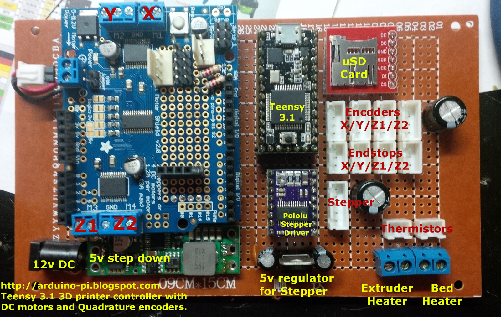
I've added a DC/DC converter for clean 5v power to the electronics (5amp).  I've also added a separate 5v linear regulator for the Extruder stepper circuitry.
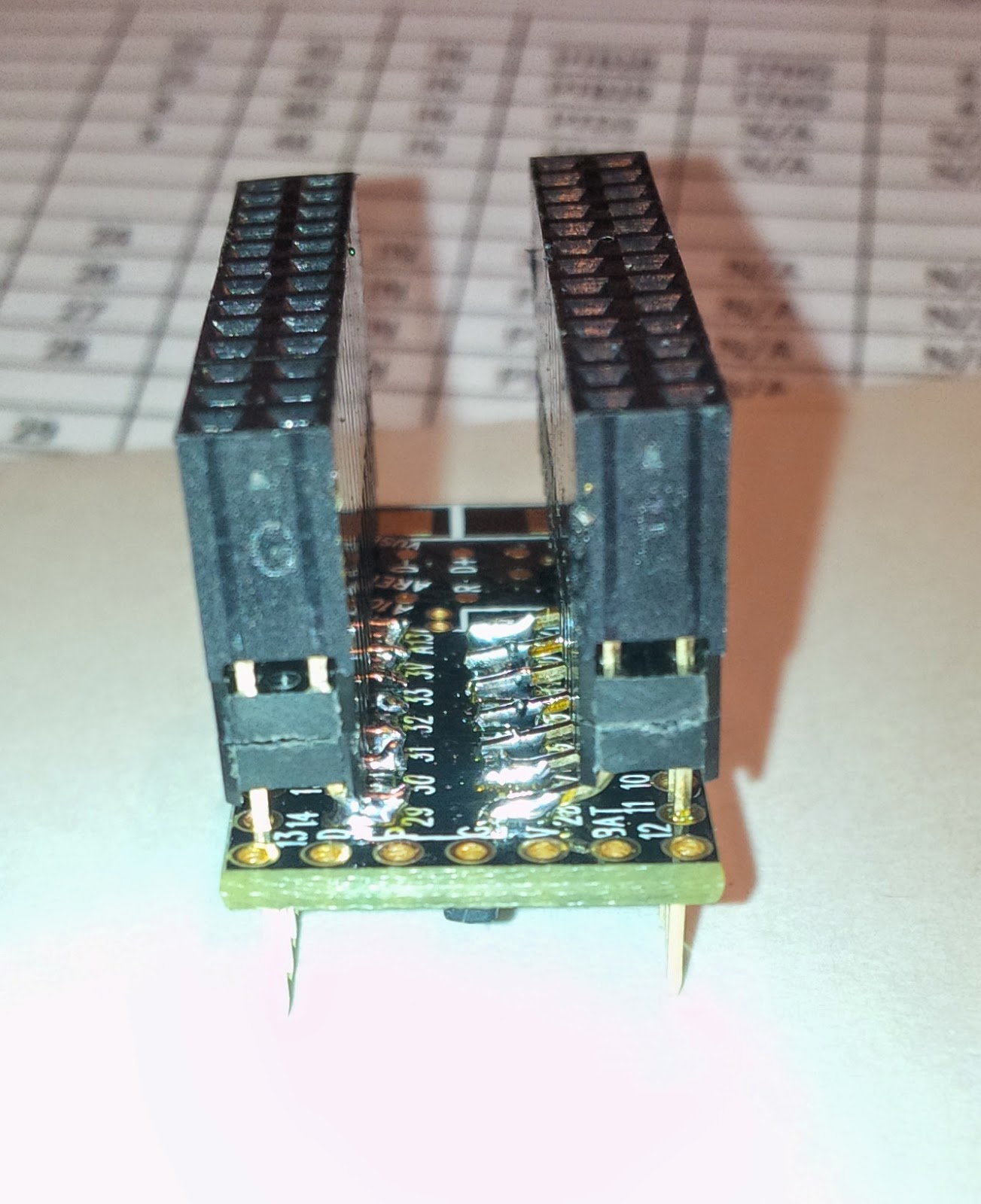
To get access to the extra pins on the bottom of the teensy, I used a dual row header, and bent the inside pins at a 90 degree angle, trimmed, and soldered.
The shot on the right shows the Real Time Clock crystal soldered into place.

And of course I use my 
legacy 3D extruder 
religiously to lay down layers of plastic "wire holders". 


This is where I wish I had kept all of my old wire wrap tools... Who knew I'd pick up electronics again after almost a 20 year hiatus.

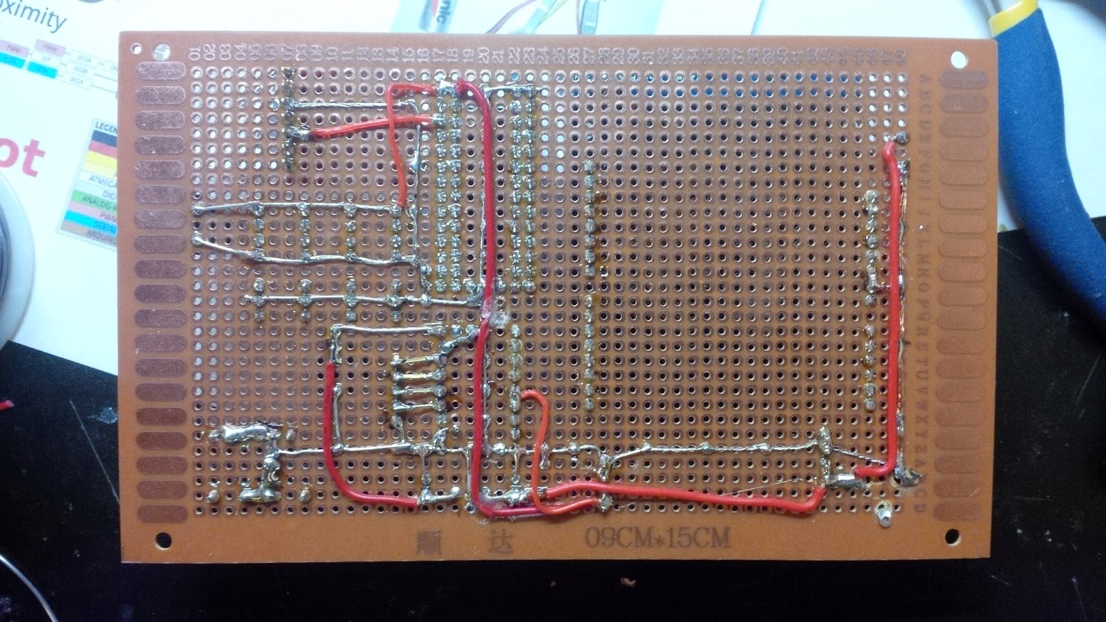
Anyway, power and ground... check. 

Now to the rest of the wires..
 

Sunday 28 December 2014

Prototype Board: DC motor/Encoder - Teensy 3.1 based 3D printer controller

This will be a short post today.  

I had mentioned putting up pictures as I go along, so I took this to show the first prototype of the controller board.

Here is the layout of my Teensy 3.1 based 3D printer controller.


As of this shot, I have not yet wired it.  Nor have I installed the analog components (power supply, heater drivers, pullup resistors, filter capacitors, etc...).  It is also missing the connector for the extruder stepper motor. 

As I described in my previous post, my motor control design is based on Adafruit's Motor Shield V2.3.  For my prototype... well... I'm using their shield, pilfered from one of my older robots. This fantastic design employs an NXP PCA9865 16 channel 12 bit PWM controller, intended to drive LEDs, but instead to  driving a pair of dual Mosfet H bridge TB6612FNG motor drivers.

The Library for this Shield works with the Teensy 3.1 just fine. (It is just I2C after all).

Ok... I'm off to wire this up... wish me luck.


Thursday 18 December 2014

Teensy 3.1 Repstrap printer with DC motor control and Flex Timer Quadrature Encoders


As I re-engage my 3D Repscrap printer project,  I have decided to replace the two 8bit AVR based  Arduino pro minis running at 16Mhz with a single  Teensy 3.132bit ARM core M0 based board running at 96Mhz.   The Teensy is significantly faster, more powerful, and still only $20USD.


I was considerably influenced to change my direction based on this incredibly detailed Blog over at Freescale Nikki  Verriddagari, a Freescale developer, managed to replace the typical Arduino Mega2560 seen in most Reprap style printers with the Teensy 3.1 inside of 3-4 weeks, as a side project.

Both the Teensy and Reprap communities rallied to assist Nikki through a few difficult spots, and huge kudos to the developer of the Teensy 3.1, Paul Stoffregen, for working on the Teacup code with Nikki and getting it debugged and working!


The Freescale MK20DX256VLH7 processor used on the Teensy has two hardware based Quadrature Decoder modules built in. There is a good appnote on how to use them at Freescale. 
"The FlexTimer is a complex, general-purpose timer module that also possesses special features dedicated to a motor control application"

While perusing the Teensy 3.1 developer's site, I came across a forum article where Trudy Benjamin had created a library to use these FTM to read two quadrature encoders.   This looked like as good as anything for a starting point.


I'm using her QuadDecode library for the X and Y axis, and have decided to manage both Z-Axis encoders through hardware interrupts. My thoughts being that the Z-Axis travel is both minimal and predictable. I believe (I've been wrong before!) that Z-Axis movement is conducted typically after a horizontal layer of X/Y is completed.  However!!!  This does not preclude error correction in the Z-Axis PIDs. If something were to bump the extruder or a collision occurred that caused the Z-Axis to change, the PID would try to correct, and the interrupts must be responsive enough to handle this. Running at 96Mhz, I'm confident enough to give this a good shot.

My Design Concept:

I'm basing my requirements loosely on the RAMPS/Mega design, but for DC motors and quadrature encoders.

There will be four DC motors:  One each for the X and Y axis, and two for the Z axis. All will have inexpensive DC brushed motors.  The X and Y axis will have linear optical encoders, while the Z axis will have rotary optical encoders. (This is a mechanical decision for MY implementation, the electronics and firmware should not care).  All motor/encoder pairs will have endstops at each end of their travel.

To manage PWM for four DC motors, as well as PWM for the Extruder heater, Bed heater, and fans, I am choosing to borrow a design from Adafruit's Motor Shield V2.3.  In this shield, they employ a PCA9865 I2C 12 bit PWM controller, driving a pair of dual Mosfet H bridge TB6612FNG motor drivers.


A standard Pololu stepper motor driver board will be used to manage the extruder.

Primary communications will be via the Teensy's USB Serial interface, however I am including a uSD card reader for future plans to read G-Code directly from uSD card.


Starting with the example pinout used in the QuadDecode library,   I have drafted up a connectivity chart and initial schematic that I will be wiring up over the next few days.


Teensy 3.1 Based 3D printer with DC motor/Quad Encoders

Next blog will include photos of the build.


Please feel free to provide constructive criticism as I journey down this path.


References:
PJRC Forum: Hardware Quadrature Code for Teensy 3.x  
PJRC: Teensy 3.1 Encoder Library
Freescale: Configuring the FlexTimer for Position and Speed Measurement with an Encoder
Freescale: PMSM Vector Control with Quadrature Encoder on Kinetis
Kinetis: K20 Sub-Family Reference Manual 
Data sheet: Supports: MK20DX64VLH7, MK20DX128VLH7, MK20DX256VLH7 
Teensy 3.1: Pulse Width Modulation 
Loglow: Interval Timer Library for Teensy 
PJRC: New I2C library for Teensy3  
PJRC: Connecting headers to those pins on the bottom of the Teensy 3.1 


Thursday 4 December 2014

Should I port SLAM to the Raspberry Pi's unused GPU on my Autonomous Rover?


Right now, I use Arduinos for motor control (PID control for encoders and dc motor) as well as aggregating sensor data and feeding the Raspberry Pi on my Autonomous Rover.

The Pi runs a live stream webcam for the rover, manages the webpage control console, and maps the environment for dead reckoning navigation.  This is a lot of work for one little CPU.

I've recently seen a few articles on using the dormant GPU on the Pi. and though that Simultaneous Localization and Mapping (SLAM) would be perfectly suited for the GPU's capabilities. Real world mapping and localization should be practically identical to Video Game based algorithms... It's been almost a year since Broadcom opened up the specs for this chip.

I would also use the GPU for calculating shortest path via A* routines. 

So... has anyone looked into this? 
 (And yes... I "Googled" it first...)


References:

Andrew Holme: Accelerating Fourier transforms using the GPU
Pete Warden: How to optimize Raspberry Pi code using its GPU
GPGPU hacking on the Pi
Hacking The GPU For Fun And Profit (Pt. 1) 
Broadcom released the specs for the VideoCore IV GPU
SLAM: Remotely-Processed Visual SLAM Using Open-Source Software