Search This Blog

Wednesday 28 May 2014

Getting AVRDUDE working on Ubuntu with Pololu AVR ISP programmer and 3.3v ATtiny

I am an UBUNTU biggot... there, I said it!

I use Ubuntu 13.10 as my primary Operating System day in and day out.  If I *have* to use something else, I have access to MS Windows XP, Windows 7, and OSX Mountain Lion through the magic of VirtualBox.  <---- you Really want to try this!!


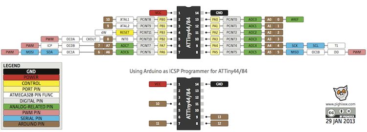
As part of my Dancing Brushbot project, I had to move out of my comfort zone in programming AVR chips.  I'm quite familiar with using the Arduino IDE to program *Arduino* boards, and have also used the IDE to program ATtiny8x chips by connecting them to an Arduino UNO ... 


For the current Brushbot project, I had made a small standalone ATtiny84 board with a builtin AVR ISP connector for programming without having to remove it from the robot.
I went to my local Robots Supply Store and purchased this Pololu AVR ISP programmer.
As I had previously programmed ATtiny chips with the UNO, I already had the proper Boards.txt configuration.

This should be simple right?


Wrong! 

  1. I plugged it in to my laptop USB port, 
  2. plugged the AVR ISP plug into the robot board
  3. From the Arduino IDE, selected  "Tools/Board/ATtiny84 (internal 8 mhz clock)"
  4. Also from the IDE  Selected Tools/Programmer AVR ISP
  5. Selected the correct USB serial port (/dev/ttyACM0)
  6. attempted to upload the compiled "Blink" sketch.

and it failed...   

AVRDUDE (the application that actually communicates with the Atmel processors) could not sync, told me to check my serial ports, etc... 

Now if you read my previous posting, you'll understand that I am RTFM challenged.


So I dug in, and did a little research, and quickly found http://openenergymonitor.org/emon/buildingblocks/avrisp

3. AVR ISP V2 - Pololu USB AVR Programmer (http://www.pololu.com/catalog/product/1300). This is quite a cheap programmer that works well on Linux Ubuntu, it can only programmed at 5v (needs 4V on MOSI pin to initialize) and requires the board to be externally powered. The following lines need to be added to programmers.txt in the Arduino Hardware folder:
avrispv2.name=AVR ISP v2
avrispv2.communication=serial

avrispv2.protocol=avrispv2
Using sudo,  I opened /usr/share/arduino/hardware/arduino/programmers.txt, and added the following 3 lines:
avrispv2.name=AVR ISP v2
avrispv2.communication=serial

avrispv2.protocol=avrispv2
I closed and reopened the Arduino IDE,  and the new programmer showed up.  I selected it from the Tools/Programmer menu, and again attempted to upload.

and it failed... 

Remember that RTFM issue? 

Looking at what I posted here from the Openenergy blog a paragraph up... 
This is quite a cheap programmer that works well on Linux Ubuntu, it can only programmed at 5v (needs 4V on MOSI pin to initialize) and requires the board to be externally powered.

This lead me to read the Pololu manual for the ARV ISP programmer (gasp!)

And  this comment on the pololu forum: 
Re: Pololu USB AVR ProgrammerPostby JeremyT » Fri Sep 13, 2013 3:34 pmYou can configure the Pololu USB AVR Programmer through Linux using PgmCmd from the Pololu USB Software Development Kit. PgmCmd is a command-line status and configuration utility. More information, such as how to compile the code, can be found in the README.txt in the SDK. By the way, I still recommend configuring it via Windows, as it would probably be easier. 
I have programmed an Atmega8U2 running at 3.3V with the Pololu USB AVR Programmer in Windows, and I do not expect there be a difference in programming with Linux, as long as the programmer is configured correctly. 
Using a level shifter, like the one you linked, would probably work. A resistor voltage divider would also suffice. However, I did not have any voltage divider when I programmed the Atmega8U2. 
- Jeremy

(Note:  as the AVR chips can run at up to 5.5v they do not need a level shifter)

I then downloaded the Pololu USB Software Development Kit for Linux. and read the Readme.txt file           (I know, eh?) 

To compile their C# applications, you need mono installed:
     sudo apt-get install libusb-1.0-0-dev mono-gmcs mono-devel libmono-winforms2.0-cil

     In the top level directory of the downloaded SDK, type "make".  


From there, I was able to cd to the pololu-usb-sdk/UsbAvrProgrammer/PgmCmd folder, and execute the AVR ISP programmer's command line utility   

./pgmcmd --list  

PgmCmd: Configuration and status utility for the Pololu USB AVR Programmer.
Version: 1.0.1.0
Options:
 -l, --list             list available devices
 -d, --device SERIALNUM (optional) select device with given serial number
 -s, --status           display complete device status
     --freq NUM         sets the ISP frequency (in units of kHz)
     --linea ID
       or --lineb ID    set serial control signal associated with line A or B.
                        Valid IDs are: none, cd, dsr, ri, dtr, rts.
                        Warning: dtr and rts are outputs: -f option is required
     --swminor HEXNUM   AVR ISP software version minor (in hex, e.g. A)
     --swmajor HEXNUM   AVR ISP software version major (in hex)
     --hw HEXNUM        AVR ISP software hardware version (in hex)
     --vddmin NUM       set minimum allowed target vdd (units of mV)
     --vddmaxrange NUM  set maximum allowed target vdd range (units of mV)
     --restoredefaults  restore factory settings
     --bootloader       put device in to bootloader (firmware upgrade) mode

then   ./pgmcmd --status  revealed... 

Serial number:                  00060244
Firmware version:               1.07
Settings:
  ISP Frequency:                200 kHz
  Line A Identity:              None
  Line B Identity:              None
  AVR ISP hardware version:     F
  AVR ISP software version:     2.A
  Target VDD allowed minimum:   4384 mV
  Target VDD allowed max range: 512 mV
Last programming:
  Error: None
  Measured Target VDD Minimum:  N/A
  Measured Target VDD Range:    N/A
SLO-scope:
  State:                        Off
  Line A output:                Off
  Line B output:                Off


So... I ran ./pgmcmd --vddmin 3200  
to set a minimum VDD value of 3.2v.. resulting in...

Serial number:                  00060244
Firmware version:               1.07
Settings:
  ISP Frequency:                200 kHz
  Line A Identity:              None
  Line B Identity:              None
  AVR ISP hardware version:     F
  AVR ISP software version:     2.A
  Target VDD allowed minimum:   3200 mV
  Target VDD allowed max range: 512 mV
Last programming:
  Error: None
  Measured Target VDD Minimum:  N/A
  Measured Target VDD Range:    N/A
SLO-scope:
  State:                        Off
  Line A output:                Off
  Line B output:                Off

I plugged the robots battery in (remember that requires the board to be externally powered comment?), plugged in the AVR ISP cable, opened the blink sketch in the Arduino IDE, and clicked the upload icon......

(drum roll please!)

The leds under the Sharp IR distance sensor came to life!!!  


Stay tuned for Funky Robotic Vibratory Dancing!


References:

Pololu USB AVR Programmer User's Guide
AVR ISP Programmers 
Stackexchange: How to use a Pololu 5v AVR ISP Programmer to program an AVR at 3.3v
forum.pololu.com: Pololu USB AVR Programmer - Ubuntu
Pololu: Pololu USB Software Development Kit
http://forum.arduino.cc/index.php?topic=73027.0;wap2
http://runawaybrainz.blogspot.ca/2013/05/arduino-pololu-usb-avr-programmer.html
http://provideyourown.com/2011/arduino-program-attiny/
http://www.open-electronics.org/arduino-isp-in-system-programming-and-stand-alone-circuits/
http://www.instructables.com/id/How-to-program-attiny-using-arduino-uno/
http://www.instructables.com/id/Using-the-Arduino-Uno-to-program-ATTINY84-20PU/
http://42bots.com/tutorials/programming-attiny84-attiny44-with-arduino-uno/
http://www.batsocks.co.uk/readme/isp_headers.htm
http://highlowtech.org/?p=1695


Tuesday 27 May 2014

Arduino: User Error -- AIN0 *IS NOT* A0

I am revisiting my code for the OSLRF01  Open Source Laser Range Finder, as the thought occurred to me that I should be using the ATmega built-in Analog Comparator to determine the rise time of the return pulse.  

I will outline the new code in an upcoming post, however.....


This post is about my failure to clearly RTFM:

In this case, it would be the  Atmel 8bit Microcontroller Datasheet specifically Section 22 on the Analog Comparator (Page 246) and Table 13-9 on page 88:

So let me state a simple fact that I ignored:

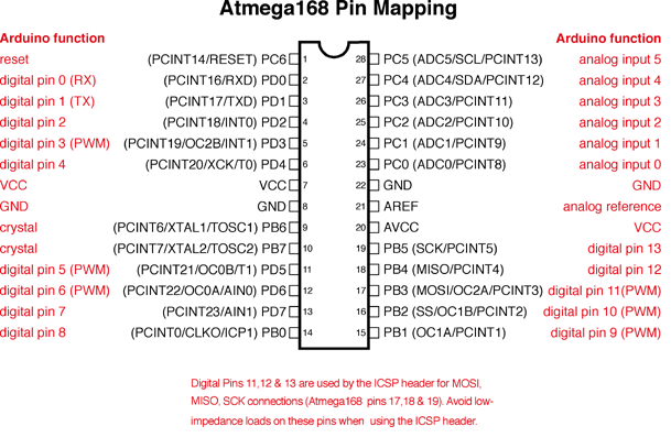
AVR digital pins AIN0 (D6), and AIN1 (D7) are NOT the same as AVR Analog pins A0 and A1.


Nick Gammon has this simple diagram on his site for using the AVR Analog Comparator, that I've looked at a dozen times:


It Clearly shows AIN0 and AIN1 associated with Digital pin D6 and D7 respectively.    Yet I continued to try using A0 as my reference voltage, and A1 as the incoming analog signal.   

 I mean *Why on god's green earth would I compare analog signals on digital pins, right?*

It was only by chance that I was reading a similarly puzzled users question on the Arduino Forum: 


Quote
It is possible to select any of the ADC7..0 pins to replace the negative input to the Analog Com-
parator. .....
 If ACME is cleared or ADEN is set, AIN1 is applied to the negative input to the Analog
Comparator.
A0 and A1  are not the same as AIN0 and AIN1.
Quote
PC1 (ADC1/PCINT9) pin  and PC0 (ADC0/PCINT8)
PCINT23 /AIN1 - pin D7  and PCINT22/OC0A/AIN0 - pin D6)
There is "working" example:
Code:
//Configure Analog Comparator, Video Input Capture
  ADCSRB &= ~(1<<ACME);
  ACSR   &= ~(1<<ACD) ;           // Analog Comparator disable off
  ACSR   |=  (1<<ACIC);

  ACSR   |=  (1<<ACIS1);          // comparator detection edge
  ACSR   |=  (1<<ACIS0);          //** 10 - falling, 11- rising:  ACSR &= ~(1<<ACIS0)
  DIDR1  |=  (1<< AIN0D);         // disable digital input buffer AIN0/1
  DIDR1  |=  (1<< AIN1D);
Digital pins 6 and 7 as comparator inputs.
BTW, should you clear a flag after printing?

<Insert the sound of a hard forehead smack here>


References:
http://www.arduino.cc/en/Reference/PortManipulation
http://www.billporter.info/2010/08/18/ready-set-oscillate-the-fastest-way-to-change-arduino-pins/
https://github.com/projectgus/digitalIOPerformance
digitalWriteFast, digitalReadFast, pinModeFast etc  <--- needs to be updated for Arduino 1.0+
https://code.google.com/p/digitalwritefast/downloads/list  <--- needs to be updated for Arduino 1.0+
http://www.lightware.co.za/shop/en/laser-sensors/24-oslrf-01.html
http://arduino.cc/en/Hacking/Atmega168Hardware
https://github.com/TMuel1123/Arduino/blob/master/FastPins/FastPins.h <--  this one looks promising but needs the pins mapped...
http://tmuel1123.blogspot.ca/2014/01/fastpinsh-or-way-to-realize-really-fast.html
http://forum.arduino.cc/index.php/topic,94534.0.html
http://www.avr-tutorials.com/comparator/utilizing-avr-analog-comparator-aco
http://www.avr-tutorials.com/sites/default/files/ATMega8515%20Analog%20Comparator_1.pdf

Wednesday 21 May 2014

Dancing Brushbot assembly...

Update on the Dancing Brushbot: 


In my last posting, I mused about the potential of making this cheap wind-up toy actually move about...
possibly avoid obstacles...  

Well, I've had some time to think and plan, and dismember the cheerful little dude...


Here is the sum of his parts.

You'll  notice the little white box lower middle of the picture.  That is the spring wound mechanism that made him dance...


It fit inside the body, in an area roughly 2.5cm high by 1.5cm wide by 1cm deep.

The is the space I have for electronics...


 This is the underside of our friendly Hexbot Nano, with the battery removed. I'll be simply connecting to the positive and negative battery wires for this build.


Opened up, you can see the miniature "pager" motor with the offset weight that vibrates the Hexbot Nano.  
I've also placed the protection diode inside the body of the Hexbots, as there was no room on the main circuit board. 


  I then hotglued the Dancing bot's feet onto the tops of the Hexbot Nano's and drilled a hole to pass the motor wires through.

Here is the blank board in it's body casing. That's it.  That's all the room I have for electronics.


Luckily, an Attiny84 in socket, as well as a power connector and the ISP header all fit exactly on the board! I couldn't have asked for a better fit!

 The Sharp GP2Y0A21YK Infrared Distance Sensor is hotglued onto the stub that held the original Dancing bot's head, and the LiPo battery is velcroed onto the front of the body.
 Here, the ATtiny84 control board is placed into the body for sizing. 
Assembled, and ready to code.   I've placed the AA battery in the picture to demonstrate the size of this guy.


Watch this space over the next few days, as I get this guy up and dancing... 

(currently having problems with balance/center of gravity... this too will be conquered)


References:

Programming an ATtiny w/ Arduino 1.0
LetsMakeRobots: Mogul - Program standalone ATtiny / ATmega chips through an Arduino
LetsMakeRobots: Ladvien - Robot Metallurgy 101 -- AVR Lesson Journal
LetsMakeRobots: attiny85 h-bridge ldr robot
LetsMakeRobots: Lumi - TinySpider
http://www.iheartrobotics.com/2009/12/upgrade-led-hexbug-hack.html


Friday 16 May 2014

Upcoming fun project with dual Brushbot and ATtiny84...

While I'm waiting on parts (extruder, beated bed,  and hotend) for my RepScrap 3D printer, I thought I would have a bit more fun...

Someone sent me this hilarious video, and it started me thinking...

I frequently attend various  vendor trade shows,  and invariably, the vendors hand out useless trinkets as advertising...  I usually do one of three things with these... 

    1) anything electronic gets tossed into the parts bin, 
    2) anything of a "toy" nature goes to my children (yes, I got that order straight) 
    3) everything else gets tossed them into the garbage.


 So I happen to have a pair of these "electronic devices" in my parts bin.  I think they are commercially known as "Hexbot Nanos

They would effectively replace the toothbrush head and pager motor in the above video....

But I also received one of these little wind up distractions to the left here...  

Mechanical spring wound clockworks makes him do a little dance...  

For some strange reason, he hadn't quite made it to the kids yet...  hmmm....


It looks like those Hexbots might just fit the bottom of his feet..... 

Maybe I could run them directly from an ATtiny84 as in THIS blog... 
yes, I know I should add a transistor to drive each motor, but when I looked up the current draw on a free running pager motor, low and behold they are around 20-40ma... well within the range of the ATtiny84 pins capability.


 Current and RPM specs:

Voltage RPM Current (free) Current (stall)
1.5V 9700 17.5mA 120mA
3.0V 18420 22mA 260mA
5.0V 31900 32.1mA 420mA


Add a Sharp IR proximity sensor onto his chest, a small LiPo battery on his back for balance, the gratuitous leds on the head, and I think we just may have ourselves the next project.... It doesn't get much simpler...

(ok, ok... yes, I'll likely wire in a connector for the AVR programmer... but that's it...  well... and maybe find another pager motor to replace the spring wound mechanism that makes him dance... but THATs it... really...

maybe...)


I thought I would put this picture in, just to show the scale... 


References and prior art:


Monday 12 May 2014

Using the Arduino PID Library for position control of X and Y axis on RepScrap printer

I've updated the test code I'm using to manage my X and Y axis DC motor / linear encoder closed loop controller. 


I am currently using the Arduino PID Library by Brett Beauregard  for this, and having great success.  Videos to come tomorrow. 

I am *NOT* going to explain what PID is, or how PID works.... I couldn't possibly do it justice.  I'll simply point you to Brett's wonderful explanation:


In the following example, I set up two axis, X and Y, each using a DC motor run from the Adafruit Motor Shield V2.  This shield provides PWM control for up to four separate DC motors via I2C communications.

I then set up two Quadrature encoders, one for each axis, using the Hardware Interrupts 0 and 1 (Arduino digital pins 2 and 3) and high speed digital port reads for one half of each encoder, and then validate the state of the other phase pin of the encoder during the interrupt routine: 
Graciously borrowed from http://forum.arduino.cc/index.php?topic=41615.20;wap2

The ZERO endstop for each axis is set up using the Arduino PinChangeInterrupt library watching a pin attached to a photo-interrupter.


I would certainly accept any advice on a proper sequence to initialize each axis to the ZERO endstop.

Right now, I arbitrarily send the carriage forward for 100ms assuming this is enough time to get on the positive side of the endstop, if we were beyond it.  Then I set my current position to the maximum possible location, and start travelling back to the endstop, knowing that once I actually reach it, the interrupt routine will Zero out my position, and initialize my PID setpoint to zero as well, thus stopping travel at ZERO. 
Is there a more efficient way of doing this? 


Inside the loop portion of my code, I run the PID controls as per the library, providing motor speed control via the Adafruit motor class, and periodically check to see if both X and Y axis have reached their goal.  At which time, I randomly select a new target for each.  When I get to the real application of this, the random selection of X and Y axis targets will be replaced by GRBL coordinates. 


And without further ado, here is my working code for precise position control in X and Y axis using the Arduino PID library:

/***************************************************************************************
*  Lin_Enc_02.ino   05-12-2014   unix_guru at hotmail.com   @unix_guru on twitter
*  http://arduino-pi.blogspot.com
*
*  This sketch allows you to run two salvaged printer carriages for X/Y axis using their 
*  linear encoder strips for tracking. 
*  This example uses the Arduino PID Library found at:
*  https://github.com/br3ttb/Arduino-PID-Library/archive/master.zip
*
*  Hardware Interrupt 0 on Digital pin2 is used to determine X-Axis position
*  Hardware Interrupt 1 on Digital pin3 is used to determine Y-Axis position
*  PinchangeInterrupt is used to identify the Zero Endstop for X and Y axis

*****************************************************************************************/

#include <Wire.h>
#include <Adafruit_MotorShield.h>
#include "utility/Adafruit_PWMServoDriver.h"
#include <PID_v1.h> 
#include <PinChangeInt.h>


#define frontstop = 100                          // Right most encoder boundary
#define backstop = 3600                         // Left most encoder boundary


// Create the motor shield object with the default I2C address
Adafruit_MotorShield AFMS = Adafruit_MotorShield(); 

// Select which 'port' M1, M2, M3 or M4. In this case, M1
Adafruit_DCMotor *XaxisMotor = AFMS.getMotor(1);
Adafruit_DCMotor *YaxisMotor = AFMS.getMotor(2);


const int XaxisENCPinA = 2;                  // X-AXIS  encoder 1 on pins 2 and 4
const int XaxisENCPinB = 4;
const int XaxisENDSTOP = 10;               // Endstop photointerrupter for X-Axis
volatile double XaxisENCPos = 0;

const int YaxisENCPinA = 3;                  // Y-AXIS  encoder 2 on pins 3 and 5
const int YaxisENCPinB = 5;
const int YaxisENDSTOP = 11;               // Endstop photointerrupter for Y-Axis
volatile double YaxisENCPos = 0;


double XaxisSpd,  YaxisSpd;                  // Carriage speed from 0-255
double XaxisPos, YaxisPos;                   // Current Carriage position

/*working variables for PID routines*/
// Tuning parameters
float KpX=0,  KpY=0;                          //Initial Proportional Gain 
float KiX=10, KiY=10;                         //Initial Integral Gain 
float KdX=0,  KdY=0;                          //Initial Differential Gain 

double XaxisSetpoint, YaxisSetpoint;      // Taget position for carriage

// Instantiate X and Y axis PID controls
PID XaxisPID(&XaxisPos, &XaxisSpd, &XaxisSetpoint, KpX, KiX, KdX, DIRECT); 
PID YaxisPID(&YaxisPos, &YaxisSpd, &YaxisSetpoint, KpY, KiY, KdY, DIRECT); 
const int sampleRate = 1; 

long int reportTime;

void setup() {
  Serial.begin(115200);
  Serial.println("Linear Encoder Test  05-12-2014");

  AFMS.begin();  // Set up Motors
  
  XaxisMotor->run(BACKWARD);                  // Bring carriage to home position. 
  XaxisMotor->setSpeed(70); 
  delay(100);                                                // Get endstop limiter working here
  XaxisMotor->run(FORWARD);                    // Bring carriage to home position. 
  XaxisMotor->setSpeed(0); 
  

  YaxisMotor->run(BACKWARD);                  // Bring carriage to home position. 
  YaxisMotor->setSpeed(70); 
  delay(100);                                                // Get endstop limiter working here
  YaxisMotor->run(FORWARD);                    // Bring carriage to home position. 
  YaxisMotor->setSpeed(0); 
  
  attachInterrupt(0, doXaxisENC, CHANGE);     // encoder pin on interrupt 0 (pin 2)
  attachInterrupt(1, doYaxisENC, CHANGE);     // encoder pin on interrupt 1 (pin 3)

  PCintPort::attachInterrupt(XaxisENDSTOP,doXaxisEndstop,FALLING); //X-axis Endstop ISR
  PCintPort::attachInterrupt(YaxisENDSTOP,doYaxisEndstop,FALLING); //Y-axis Endstop ISR

  randomSeed(analogRead(0));                          // Used to select random setpoints for testing

  XaxisPID.SetMode(AUTOMATIC);                //Turn on the PID loop 
  XaxisPID.SetSampleTime(sampleRate);         //Sets the sample rate 

  YaxisPID.SetMode(AUTOMATIC);                //Turn on the PID loop 
  YaxisPID.SetSampleTime(sampleRate);         //Sets the sample rate 

  reportTime = millis()+2000;
}

void loop() {
uint8_t oldSREG = SREG;                           // Store interrupt status register

  cli();
  XaxisPos = XaxisENCPos;  
  YaxisPos = YaxisENCPos;
  SREG = oldSREG;                                    // Restore interrupt status register
  

  // Temporary to create random X and Y axis setpoints for testing
  if(millis() > reportTime) {                               // Only validate this every 2 seconds
    if(XaxisPos == XaxisSetpoint && YaxisPos == YaxisSetpoint) {   
      // If both X-axis and Y-axis have reached their target - get new targets
      XaxisSetpoint =  random(200,3500);             // Keep target within bounds of Endpoints
      YaxisSetpoint =  random(200,3500);             // Keep target within bounds of Endpoints
    }    
    reportTime = millis()+2000;
}
  
  
  // Manage X-axis positioning
  XaxisPID.Compute();                          //Run the PID loop 
  if(XaxisSetpoint < XaxisPos) XaxisMotor->run(BACKWARD);  // Determine direction of travel
  else  XaxisMotor->run(FORWARD);      
  XaxisMotor->setSpeed(XaxisSpd);              // Apply PID speed to motor


  // Manage Y-axis positioning
  YaxisPID.Compute();                          //Run the PID loop 
  if(YaxisSetpoint < YaxisPos) YaxisMotor->run(BACKWARD);  // Determine direction of travel
  else  YaxisMotor->run(FORWARD);      
  YaxisMotor->setSpeed(YaxisSpd);              // Apply PID speed to motor

}


/***************************************************************************************
The following code was taken from   http://forum.arduino.cc/index.php?topic=41615.20;wap2
to utilize the fast port based encoder logic.  Thank you Lefty!
please go there for a full explanation of how this works.  I have truncated the comments 
here for brevity.

***************************************************************************************/

void doXaxisENC() {                                  // ************** X- AXIS ****************
    if (PIND & 0x04) {                              // test for a low-to-high interrupt on channel A, 
        if ( !(PIND & 0x10)) {                      // check channel B for which way encoder turned, 
           XaxisENCPos = ++XaxisENCPos;               // CW rotation
          }
        else {
           XaxisENCPos = --XaxisENCPos;               // CCW rotation
          }
    }
    else {                                          // it was a high-to-low interrupt on channel A
        if (PIND & 0x10) {                          // check channel B for which way encoder turned, 
           XaxisENCPos = ++XaxisENCPos;               // CW rotation
           }
        else {
           XaxisENCPos = --XaxisENCPos;               // CCW rotation
        }
     }
}                                                   // End of interrupt code for encoder #1


void doYaxisENC(){                                  // ************** X- AXIS ****************
  if (PIND & 0x08) {                                // test for a low-to-high interrupt on channel A, 
     if (!(PIND & 0x20)) {                          // check channel B for which way encoder turned, 
      YaxisENCPos = ++YaxisENCPos;                  // CW rotation
     }
     else {
      YaxisENCPos = --YaxisENCPos;                  // CCW rotation
     }
  }
  else {                                            // it was a high-to-low interrupt on channel A
     if (PIND & 0x20) {                             // check channel B for which way encoder turned, 
      YaxisENCPos = ++YaxisENCPos;                  // CW rotation
      }
     else {
      YaxisENCPos = --YaxisENCPos;                  // CCW rotation
     }
  }
}                                                   // End of interrupt code for encoder #2


void doXaxisEndstop() {
  XaxisENCPos=0;                                    // X-Axis Endstop indicates ZERO position 
}

void doYaxisEndstop() {
  YaxisENCPos=0;                                    // Y-Axis Endstop indicates ZERO position 
}

            https://github.com/michaeljball/RepScrap

Updated diagram for reference:


References:

DIYDrones: Tutorial series for new Arduino PID library
http://brettbeauregard.com/blog/2011/04/improving-the-beginners-pid-introduction/
http://robotics.stackexchange.com/questions/1232/how-can-i-use-the-arduino-pid-library-to-drive-a-robot-in-a-straight-line
Tim Wescott's PID without a PHD
http://abigmagnet.blogspot.ca/2008/10/dc-motor-control-part-one.html
http://www.pdx.edu/nanogroup/sites/www.pdx.edu.nanogroup/files/2013_Arduino%20PID%20Lab_0.pdf

https://www.youtube.com/watch?v=ZZYgZjMnGXU
https://www.youtube.com/watch?v=wbmEUi2p-nA
http://blog.solutions-cubed.com/pid-motor-control-with-an-arduino/
http://forum.arduino.cc/index.php/topic,45169.0.html

http://playground.arduino.cc/Code/PIDLibrary
http://playground.arduino.cc/Code/PIDAutotuneLibrary

Arduino Playground: PinChangeInterrupt Library
https://code.google.com/p/arduino-pinchangeint/downloads/list

LetsMakeRobots: PID Control by Big Face
LetsMakeRobots: PID Tutorials for Line Following by Enigmerald
LetsMakeRobots: PID without a PHD by BDK6
LetsMakeRobots: Using Motor Encoders to Control Speed by Oddbot