
You guys are both supportive and educational at the same time.
Yes... many of you either told me not to bother because I was simply reinventing the wheel (I actually appreciate that the most because many of you provided links to prior art!), or that I was just plain foolish to attempt this... (but if you are going to criticize, back it with facts/links)...
But MANY of you (over 100 as of this writing) have provided me with positive reinforcement, and sent me links and articles showing others who have succeeded on this journey in one way or another.
I just want to talk a minute about the differences between a "Stepper Motor" a "DC Motor" and a "Servo Motor".
I've linked each of the above to Wikipedia so that I don't have to go into great detail of how each actually works. I'm more interested in the differences each presents in the context of fine grain positioning control.
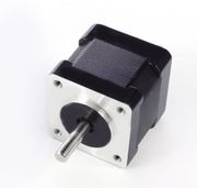 A Stepper motor has multiple coils that when energised in a certain sequence, produces defined accurate "steps" of the shaft. The NEMA 17 Stepper Motor shown here, seems to be the DIY 3D printer industry's favorite. It provides 1.8° per step accuracy. As long as your software can initialize the linear travel with endstop switches, mechanical or optical, then it will know at all times where along the axis it was left. There is little issue with "drift". When you cut the power to a stepper motor, it stays exactly where you placed it. Yes, of course you can "push" the carriage without power but for the most part an energized step will place the shaft in a known spot. Speed is managed by the frequency in which you cycle the steps.
 A DC motor, on the other hand is pretty much "free running". You apply a DC voltage to the winding, and the shaft will spin in one direction. Reverse the polarity and the shaft will spin in the other direction. Torque is based on electric current capabilities, and is a factor of the wire gauge and number of windings. Speed is related to the voltage applied. Most DC motors in a control context are driven via Pulse Width Modulation or PWM, but still have no feedback as to the position of the shaft, or in my case linear carriage. When you remove power from a DC motor, it will coast until it stops. To remedy this, you need to employ Dynamic Braking. Accuracy is non Existent.

A Servo Motor, starts with a DC motor, but provides a feedback mechanism for the angle of rotation. The hobbyist style servos shown to the right here, rely on a potentiometer, attached to the motor shaft by gears. The position of the shaft is directly related to the value of the potentiometer.
Commercial Servo Motors will employ magnetic, electric, or optical Encoders to sense rotational (or linear) movement, and provide this feedback to a servo controller.
A Servo Motor is basically a closed loop system that provides direct feedback to the controller upon any movement of the shaft. Accuracy is a product of the resolution of the encoder in use.
To that end, what I am proposing in my project, is to make a set of Linear Servo Motors.
I will drive them with Pulse Width Modulation as a DC motor. I will provide feedback, monitoring the encoder position through Interrupts, and thus essentially create a linear servo motor. In addition, I will apply the appropriate functions to slow the carriage in advance of the destination so as not to overrun the target. Photo interrupters will be used at each end of the carriage for periodic self calibration.
Here are a few of the links shared with me:

Apparently the GeckoDrive is a popular solution in this space, it takes the outputs meant for a stepper, and manages a DC motor / encoder loop.
Then there's Rapy, a DC motor powered 3D printer made in Korea
It uses two DC Gear motors and one Rotary Optical Encoder per axis.

Somewhat unrelated, but a very interesting belt drive linear motion system using 80/20 extrusion as the linear rail.
More to read:
Converting an Ordinary DC Motor to a Servomotor
http://www.motioncontroltips.com/category/encoders/l-encoders/
https://www.youtube.com/watch?v=wBnbQrs6JsQ
http://blog.machinekit.io/p/machinekit_16.html?m=1
(http://www.geckodrive.com/geckodrive-brush-dc-drives/g320x.html
http://www.geckodrive.com/gecko/images/cms_files/images/G320XStepDirectionCircuit.jpg \
Makeatronics: Building a 3D printer
Makeatronics: 3D Printer Motor Control - Part 1
https://groups.google.com/forum/#!topic/makerbot/hgdUMBRkU38
http://martingautron.com/inputs/books/diy/3d-print.html
https://www.youtube.com/user/ENKTechnologies
GeckoDrive: Step Motor Basics Guide
"Very great post.Thanks for sharing this post.
ReplyDeleteLooking for reliable DC motors? Tomson Electronics offers a premium selection perfect for various industrial and hobbyist applications. Known for their simplicity, durability, and cost-effectiveness, Motors are ideal for precise control and continuous rotation. Visit Tomson Electronics for all your motor and electronic component needs!"