Search This Blog

Tuesday, 29 April 2014

Arduino Sketch to manage high resolution - high speed linear encoders


In the ongoing saga of building my RepStrap 3D printer from salvaged printer parts...

The first axis is sorted out:


This is the printhead carriage salvaged out of a inkjet printer.  It basically consists of a DC gear motor driving a tensioned belt, pulling the print carriage across a high resolution optical encoder strip


There have been plenty of people do this before me, but this is my kick at repurposing salvaged printer parts.  


This is the print head circuit board from the carriage.  In the center, you will see the solder pads for the Optical Encoder Sensor.  My original intent was to keep the flat cables intact, and pull the signals off of those, but at about 50mil pitch... I can't even think about soldering that... 
(yeah, I'm getting old)

As they have already done the work of wiring the IR LED with a resistor to VCC, all I really need is four wires.  VCC/GND/Encoder Phase A and B. 
The Optical Encoder provides logic level outputs to the Interrupt pins on the Arduino.  The sketch below only addresses the X-AXIS for demonstration purposes, and only uses one Interrupt on Phase A, while polling the signal level on Phase B.  This provides half the resolution capable from this Quadrature encoder. 

In a future article, we will demonstrate using PinChange Interrupts to get the full resolution from this arrangement.

/***************************************************************************************
*  Lin_Enc_01.ino   04-29-2014   unix_guru at hotmail.com   @unix_guru on twitter
*  http://arduino-pi.blogspot.com
*
*  This sketch allows you to run two salvaged printer carriages for X/Y axis using their 
*  linear encoder strips for tracking. 
*  Both interrupt routines are below, but for the sake of demonstration, I've only set up
*  the X-AXIS for now.
*
*****************************************************************************************/

#include <Wire.h>
#include <Adafruit_MotorShield.h>
#include "utility/Adafruit_PWMServoDriver.h"

#define frontstop = 100            // Right most encoder boundary
#define backstop = 3600            // Left most encoder boundary


// Create the motor shield object with the default I2C address
Adafruit_MotorShield AFMS = Adafruit_MotorShield(); 

// Select which 'port' M1, M2, M3 or M4. In this case, M1
Adafruit_DCMotor *myMotor = AFMS.getMotor(1);


const int encoder1PinA = 2;        // X-AXIS  encoder 1 on pins 2 and 4
const int encoder1PinB = 4;
volatile int encoder1Pos = 0;

const int encoder2PinA = 3;        // Y-AXIS  encoder 2 on pins 3 and 5
const int encoder2PinB = 5;
volatile int encoder2Pos = 0;

boolean CarriageDir = 0;           // Carriage Direction '0' is Right to left
byte spd = 220;                    // Carriage speed from 0-255
int newpos = 0;                    // Taget position for carriage
int posrchd = 1;                   // Flag for target reached

int Pos1, Pos2;


void setup() {
  Serial.begin(115200);
  Serial.println("Linear Encoder Test  04-29-2014");

  AFMS.begin();  // Set up Motors
  
  myMotor->run(BACKWARD);        // Bring carriage to home position. 
  myMotor->setSpeed(spd); 
  delay(100); 
  myMotor->run(FORWARD);        // Bring carriage to home position. 
  myMotor->setSpeed(0); 
  
  attachInterrupt(0, doEncoder1, CHANGE);  // encoder pin on interrupt 0 (pin 2)
  // attachInterrupt(1, doEncoder2, CHANGE);  // encoder pin on interrupt 1 (pin 3)
  
  randomSeed(analogRead(0));
}

void loop() {
static int oldPos1, oldPos2;
uint8_t oldSREG = SREG;

uint8_t i;

  cli();
  Pos1 = encoder1Pos;  
  Pos2 = encoder2Pos;
  SREG = oldSREG;
  
  if(Pos1 != oldPos1){
     Serial.print("Encoder 1=");
     Serial.println(Pos1,DEC);
     oldPos1 = Pos1;
  }
  if(Pos2 != oldPos2){
     Serial.print("Encoder 2=");
     Serial.println(Pos2,DEC);
     oldPos2 = Pos2;
  }  
  

  //sweep_carriage();
  
  if(posrchd) {                           // If target has been reached clear flag, and get new target
    newpos =  random(200,3500);
    posrchd = 0;
  }    
    
  posrchd = go_to_target(newpos);
  
}


/***************************************************************************************
The following code was taken from   http://forum.arduino.cc/index.php?topic=41615.20;wap2
to utilize the fast port based encoder logic.  Thank you Lefty!
please go there for a full explanation of how this works.  I have truncated the comments 
here for brevity.
***************************************************************************************/
void doEncoder1() {                                  // ************** X- AXIS ****************
    if (PIND & 0x04) {                              // test for a low-to-high interrupt on channel A, 
        if ( !(PIND & 0x10)) {                      // check channel B for which way encoder turned, 
           encoder1Pos = ++encoder1Pos;               // CW rotation
           PORTD = PIND | 0x40;                     // set direction output pin to 1 = forward, 
          }
        else {
           encoder1Pos = --encoder1Pos;               // CCW rotation
           PORTD =PIND & 0xBF;                      // Set direction output pin to 0 = reverse, 
          }
    }
    else {                                          // it was a high-to-low interrupt on channel A
        if (PIND & 0x10) {                          // check channel B for which way encoder turned, 
           encoder1Pos = ++encoder1Pos;               // CW rotation
           PORTD = PIND | 0x40;                     // Set direction output pin to 1 = forward, 
           }
        else {
           encoder1Pos = --encoder1Pos;               // CCW rotation
           PORTD =PIND & 0xBF;                      // Set direction output pin to 0 = reverse, 
           }
         }
    PORTD = PIND | 0x80;                            //  digitalWrite(encoderstep, HIGH);   generate step pulse high
    PORTD = PIND | 0x80;                            //  digitalWrite(encoderstep, HIGH);   add a small delay
    PORTD = PIND & 0x7F;                            //  digitalWrite(encoderstep, LOW);    reset step pulse
}                                                   // End of interrupt code for encoder #1
                                                   
void doEncoder2(){                                  // ************** X- AXIS ****************
  if (PIND & 0x08) {                                // test for a low-to-high interrupt on channel A, 
     if (!(PIND & 0x20)) {                          // check channel B for which way encoder turned, 
      encoder2Pos = ++encoder2Pos;                  // CW rotation
      PORTB = PINB | 0x01;                          // Set direction output pin to 1 = forward, 
     }
     else {
      encoder2Pos = --encoder2Pos;                  // CCW rotation
      PORTD =PIND & 0xFE;                           // Set direction output pin to 0 = reverse, 
     }
  }
  else {                                            // it was a high-to-low interrupt on channel A
     if (PIND & 0x20) {                             // check channel B for which way encoder turned, 
      encoder2Pos = ++encoder2Pos;                  // CW rotation
      PORTB = PINB | 0x01;                          // Set direction output pin to 1 = forward, 
      }
     else {
      encoder2Pos = --encoder2Pos;                  // CCW rotation
      PORTB =PINB & 0xFE;                           // Set direction output pin to 0 = reverse, 
     }
  }
  PORTB = PINB | 0x02;                              // digitalWrite(encoder2step, HIGH);   generate step pulse high
  PORTB = PINB | 0x02;                              // digitalWrite(encoder2step, HIGH);   used to add a small delay
  PORTB = PINB & 0xFD;                              // digitalWrite(encoder2step, LOW);    reset step pulse
}                                                   // End of interrupt code for encoder #2


/***************************************************************************************
go_to_target() determines the distance and direction from current position to target 
position, then maps speed to decellerate close to the target so as not to overshoot.
***************************************************************************************/


int go_to_target(int target)
{
  int temp = 0;
  int delta = abs(Pos1-target);                   // Distance to target
  spd = map(delta,3600,0,255,150);                // Decellerate as you get closer
  if(target < 3600 && target > 100) {
     if(Pos1 < target) {
       myMotor->run(FORWARD);
       myMotor->setSpeed(spd); 
       temp = 0;
     } else if(Pos1 > target) {
       myMotor->run(BACKWARD);
       myMotor->setSpeed(spd); 
       temp = 0;
     }  else temp =1;
  }
  return temp;
}


/***************************************************************************************
sweep_carriage() is just a test routine to track back and forth testing overshoot. 
I will likely remove it soon.
***************************************************************************************/

void sweep_carriage()
{
    if(CarriageDir == 0) {              // Carriage Moving Right to Left
    if (Pos1 < 3600) {      
      myMotor->run(FORWARD);
      if (Pos1 > 3400) { 
       myMotor->setSpeed(spd-80); 
      } else myMotor->setSpeed(spd);  
    } else {      
      myMotor->setSpeed(0);  
      CarriageDir = !CarriageDir;  
    }
  } else {                              // Carriage Moving Left to Right
    if (Pos1 > 100) {
      myMotor->run(BACKWARD);
      if (Pos1 < 300) { 
       myMotor->setSpeed(spd-80); 
      } else myMotor->setSpeed(spd);  
     } else {      
      myMotor->setSpeed(0);  
      CarriageDir = !CarriageDir;  
    }
  }
}


This is the endstop sensor circuit.  I haven't wired it up to the Arduino as yet, but it is pretty straight forward. 


In the true nature of this project, I searched for a used motor controller to go with my Arduino .   Pictured here, is the Adafruit I2C Motor Shield V2 that was on my original robot.  This project will breath new life into it. 

This is a wonderful board in that it contains TWO dual h-bridge FET drivers for four DC motors, or two steppers, or one stepper and two motors... 


Wiring up the Optical Encoder.  Only four wires are needed...


12volt DC gear motor used to drive the carriage assembly.


References:

http://playground.arduino.cc/Main/RotaryEncoders#OnSpeed
http://reprap.org/wiki/Optical_encoders_01
http://mechatronics.mech.northwestern.edu/design_ref/sensors/encoders.html
http://forum.arduino.cc/index.php/topic,17695.0.html

Friday, 25 April 2014

PenguinBot Self Defence - or How to Arm a Penguin


Over on Hack-A-day, one of the readers joked that I should have Nerf Launchers on the PenguinBot:


And given that today *IS* World Penguin Day , I thought I would spend some time this weekend to add some more playfulness to PenguinBot.
(Disclaimer: I am not affiliated with World Penguin Day or GreenPeace. I apologise if you find this article is in poor taste.)

In a previous update, I had mentioned that I was working on changing Operating Modes from full manual, to Wandering with Object Avoidance, to Following a light with sound activation or Hand Claps.  

I live in a house with three young children...  There is no such thing as "Ambient Sound" in my house to set a reasonable threshold.  (Seriously!!!) 


Additionally, Penguins were not meant to be tethered!  Not even for programming! 

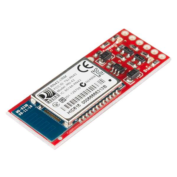
So... I've installed Bluetooth!  

I can now command this Penguin from the comfort of my chair! 


And to appease the readers of Hack A Day ....  
I'm installing a Penguin Self Defence system. 

No more will my PenguinBot be at the mercy of marauding sharks! 

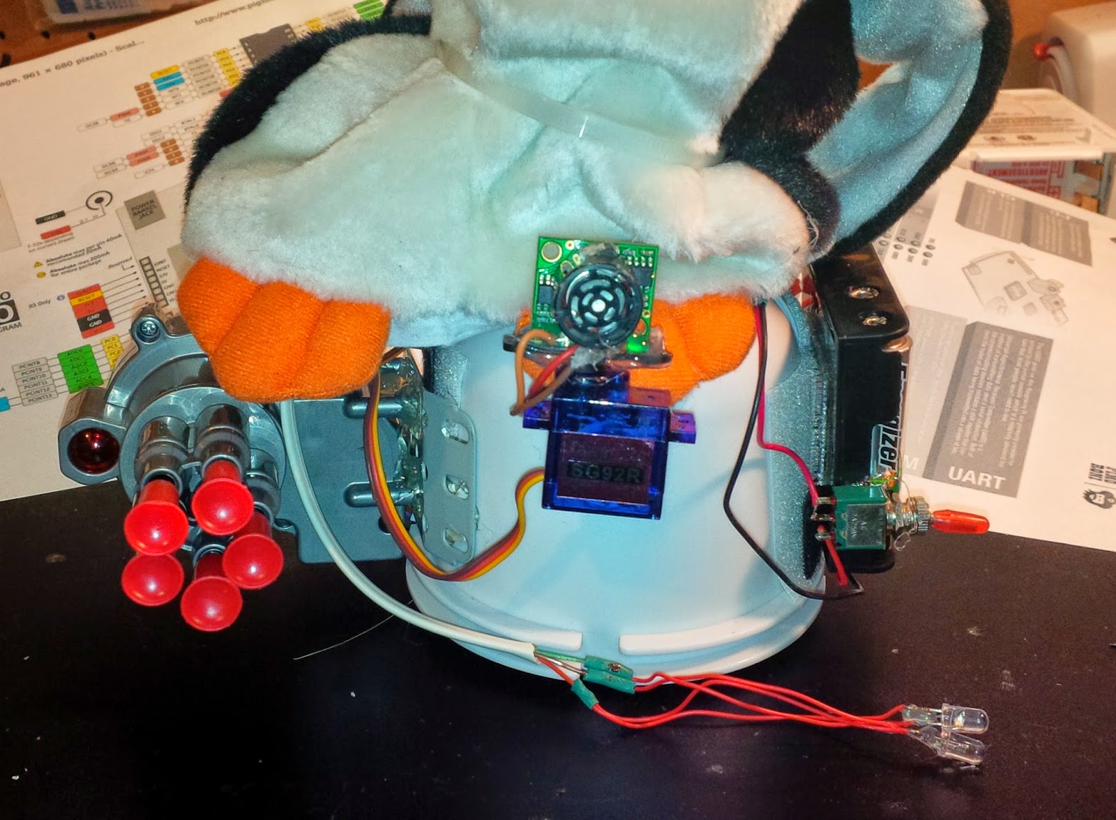
I found this in my junk drawer.  I believe it came off of a kids remote  control car. It has a simple geared DC motor.
As I only need to run it in one direction, I can turn it on and off with a transistor.  


As you can see here, the Nerf Launcher fits nicely on the opposite side as the battery pack.  AND as an added bonus, it offsets the weight of the batteries which had the annoying effect of causing the forward motion to pull to the left. 

Below find the new and improved schematic diagram of PenguinBot V2.0.


I will be wiring this up over the weekend, adding some sequencing to randomly shoot in the direction of bright lights, and uploading the videos.

Cheers, and have a great weekend.  You bet I will...


References:
http://worldpenguinday.com/
http://playground.arduino.cc/Learning/Tutorial01
http://www.instructables.com/id/Android-talks-to-Arduino/
http://learn.adafruit.com/downloads/pdf/adafruit-arduino-lesson-13-dc-motors.pdf
https://sites.google.com/site/stembotics/projects/bluetooth
http://en.wikipedia.org/wiki/Obstacle_avoidance
http://www.instructables.com/id/Arduino-Object-Avoidance-Robot/

Wednesday, 23 April 2014

Followup on 3D printer from Scavenged DC Motor / Encoders Blog

One word...  Wow!

You guys are both supportive and educational at the same time.  

Yes... many of you either told me not to bother because I was simply reinventing the wheel (I actually appreciate that the most because many of you provided links to prior art!), or that I was just plain foolish to attempt this... (but if you are going to criticize, back it with facts/links)...

But MANY of you (over 100 as of this writing) have provided me with positive reinforcement, and sent me links and articles showing others who have succeeded on this journey in one way or another.

I just want to talk a minute about the differences between a "Stepper Motor"  a "DC Motor" and a "Servo Motor".  

I've linked each of the above to Wikipedia so that I don't have to go into great detail of how each actually works.  I'm more interested in the differences each presents in the context of fine grain positioning control.


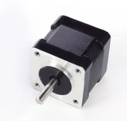
A Stepper motor has multiple coils that when energised in a certain sequence, produces defined accurate "steps" of the shaft. The NEMA 17 Stepper Motor shown here, seems to be the DIY 3D printer industry's  favorite. It provides 1.8° per step accuracy. As long as your software can initialize the linear travel with endstop switches, mechanical or optical, then it will know at all times where along the axis it was left. There is little issue with "drift".  When you cut the power to a stepper motor, it stays exactly where you placed it. Yes, of course you can "push" the carriage without power but for the most part an energized step will place the shaft in a known spot.  Speed is managed by the frequency in which you cycle the steps.


A DC motor, on the other hand is pretty much "free running".  You apply a DC voltage to the winding, and the shaft will spin in one direction.  Reverse the polarity and the shaft will spin in the other direction.  Torque is based on electric current capabilities, and is a factor of the wire gauge and number of windings.  Speed is related to the voltage applied.  Most DC motors in a control context are driven via Pulse Width Modulation or PWM, but still have no feedback as to the position of the shaft, or in my case linear carriage.  When you remove power from a DC motor, it will coast until it stops.  To remedy this, you need to employ Dynamic Braking. Accuracy is non Existent.


A Servo Motor, starts with a DC motor, but provides a feedback mechanism for the angle of rotation.  The hobbyist style servos shown to the right here, rely on a potentiometer, attached to the motor shaft by gears.  The position of the shaft is directly related to the value of the potentiometer. 

Commercial Servo Motors will employ magnetic, electric, or optical Encoders to sense rotational (or linear) movement, and provide this feedback to a servo controller. 

 A Servo Motor is basically a closed loop system that provides direct feedback to the controller upon any movement of the shaft.  Accuracy is a product of the resolution of the encoder in use.


To that end, what I am proposing in my project, is to make a set of Linear Servo Motors.
I will drive them with Pulse Width Modulation as a DC motor.  I will provide feedback, monitoring the encoder position through Interrupts, and thus essentially create a linear servo motor.  In addition, I will apply the appropriate functions to slow the carriage in advance of the destination so as not to overrun the target. Photo interrupters will be used at each end of the carriage for periodic self calibration.


Here are a few of the links shared with me:

Here is an example of a Thing-o-matic makerbot 3d printer with DC motors and linear encoders:


Apparently the GeckoDrive is a popular solution in this space, it takes the outputs meant for a stepper, and manages a DC motor / encoder loop.


Then there's Rapy, a DC motor powered 3D printer made in Korea
It uses two DC Gear motors and one Rotary Optical Encoder per axis.


Somewhat unrelated, but a very interesting belt drive linear motion system using 80/20 extrusion as the linear rail.


More to read:

Converting an Ordinary DC Motor to a Servomotor
http://www.motioncontroltips.com/category/encoders/l-encoders/
https://www.youtube.com/watch?v=wBnbQrs6JsQ
http://blog.machinekit.io/p/machinekit_16.html?m=1
(http://www.geckodrive.com/geckodrive-brush-dc-drives/g320x.html
http://www.geckodrive.com/gecko/images/cms_files/images/G320XStepDirectionCircuit.jpg \
Makeatronics: Building a 3D printer
Makeatronics: 3D Printer Motor Control - Part 1
https://groups.google.com/forum/#!topic/makerbot/hgdUMBRkU38
http://martingautron.com/inputs/books/diy/3d-print.html
https://www.youtube.com/user/ENKTechnologies
GeckoDrive: Step Motor Basics Guide


Using DC Motors and Encoders for 3D printer: Challenging the norm!

http://www.nextdayreprap.co.uk/wiring-reprap-prusa-mendel-build-manual/Every 3D printer I've seen 
(please correct me if I've missed something!) 
uses stepper motors for X/Y/Z axis. 


The RepRap firmware assume that you are using steppers in your build.


That said, RepRap does introduce the concept of "RepStrap

(from http://reprap.org/wiki/Category:RepStrap)


repstrap is a 3D printer cobbled together from whatever parts you can find, which will eventually allow you to print the parts for a reprap machine, or to simply use as a stand alone machine. Derived from the term bootstrap, as in "to pull yourself up by your bootstraps"A RepStrap is a open-hardware rapid prototyping machine which is made by fabrication processes which aren't under the RepRap umbrella yet. These are becoming less and less common as RepRap printed parts become more available, but are still an option. You can build a 3D printer RepStrap using a tablesaw, orusing a lasercutter, and use this to make fun, beautiful, useful things.


Old commercial ink/laser printers used to use stepper motors too.   

These printers typically got resolutions of 300dpi (0.08mm)  or 600dpi (0.04mm)


But....  Newer printers, say within the last decade, use DC motors with a "linear strip encoder".   And these printers typically get better than 1200dpi (0.02mm) 


(yes, I know they use interpolation to get this resolution, but work with me here...)


According to WikiPedia:  Optical linear encoders[1][2] dominate the high resolution market and may employ shuttering/MoirĂ©diffraction or holographic principles. Typical incremental scale periods vary from hundreds down to sub-micrometre and following interpolation can provide resolutions as fine as a nanometre.
And... 

Reprap already has a reference to these... 


OverviewFor those who enjoy scavenging, many components useful for constructing 3D printers can be found in inkjet printers. This often includes optical encoders and strips. This page gives information on finding and using these items.
Finding printers with linear optical encoders in themCheap inkjet printers can be obtained from garage sales or recycling centers. Do not get laser printers, since they do not have the right optical components in them. Not all inkjet printers have optical encoders and strips in them. It is easy to tell by opening the lid (as if to change the ink). You should see a grey plastic strip close to the shiny metal rod and running parallel to it. The printers that people sell cheaply or recycle generally are somewhat inky inside. Do not get ink on the optical strip, though you may be able to clean it off.
The strip runs through the optical sensor, which may be quite hidden. It is probably on the back side of the assembly that holds the ink cartridges.

So...

I'm upping my game.  My original goal was to simply copy a basic 3D printer using as much salvaged parts as I could, a few stepper motors, linear rails, switches, etc...  

Had I done my research up front, I probably would not have even started this project, however... I have started, and am facing a new challenge...

My NEW GOAL is to create a 3D printer using DC motors and the salvaged Optical Encoder strips.  

A simple test on the arduino with a pololu dual h-bridge quickly had two printer heads tracking back and forth on their carriages within minutes of wiring them up to their native cables.  I haven't accounted for overrun yet, so they oscillate like crazy before getting to their destination, but this is DEFINITELY doable.


I will likely start with Marlin Firmware and write a hardware abstraction to convert stepper motor output (steps/inch, etc...) to run a closed loop DC motor with Encoder Strip feedback.  


Any suggestions or prior art welcome! 


Let's call these two videos  --- 

Inspiration....    


References:

http://www.nextdayreprap.co.uk/wiring-reprap-prusa-mendel-build-manual/
http://en.wikipedia.org/wiki/Stepper_motor
http://reprap.org/wiki/Firmware
http://reprap.org/wiki/Category:RepStrap
http://benkrasnow.blogspot.ca/2010/02/linear-position-tracking-with.html
http://hackaday.com/2009/11/12/linear-optical-encoder/
http://reprap.org/wiki/Optical_encoders_01
http://www.electromate.com/db_support/downloads/lin.pdf
http://mil.ufl.edu/projects/gnuman/gnuman_pre2005/spec_sheets/heds_encoder.pdf
https://www.youtube.com/watch?v=0QLZCfqUeg4
http://makezine.com/2009/11/11/linear-optical-encoder-from-printer/
http://junkplusarduino.blogspot.ca/p/svg-image-plotter.html
http://madpenguin.ca/blog/2011/05/14/use-an-inkjet-printer-to-learn-emc2-and-servo-motor-control-part-1/
Arduino.cc: Agilent Optical encoder